_GOTOBOTTOM
Ships by Class/Type: Destroyers
This forum covers all types of destroyers from all eras.
Fletcher Class Difficult Question
Hatter50
Visit this Community
North Carolina, United States
Joined: June 17, 2006
KitMaker: 478 posts
Model Shipwrights: 82 posts
Posted: Friday, January 30, 2009 - 11:24 AM UTC
Hey Guys,

I've got a Fletcher Class Destroyer question. It's a difficult one.....so "stand by". This info is for the Revell 1/144 Kit, it begs for detail.

I'm looking for photos/a drawing/or persoanl memory of what Fletcher condenser intakes look like and generally where they are located..............or a fairly educated guess to what they look like. Looking at the USS Abbot's general plans, I see where they "might" have one located in each engineroom, on the opposite side of the condenser exhaust (just under the waterline). It would "Appear" that it might be a round intake with a screen over it on the lower hull not too far from the keel. Any ideas? Not too many photos of that area that i can find (like it's a national secret). (Tried the "Floating Drydock" route. Dry hole.)

Here is a photo of a scale Titanic hull (upside down) showing square intakes:


Here is a photo of a civilan ship with a square intake:


Here is a photo of a civilan ship with a round intake:


I'm not looking to take up too much of anyone's time on this, just maybe it rings a bell in the back of your head. I think that the Fletchers intakes are a bit more under the ship than these photos here.

Thanks

Regards
Steve


Admhawk
Visit this Community
Ontario, Canada
Joined: November 06, 2007
KitMaker: 32 posts
Model Shipwrights: 27 posts
Posted: Friday, January 30, 2009 - 04:09 PM UTC
The Floating Drydock has Docking plans listed.

Bu-DD445-1/4 USS FLETCHER DD445 WW2 DOCKING PLAN 1/48 $13.00

Contact them and see if this sheet has what you want. Docking plans usually have the vent locations and sometimes the shapes/sizes. It is needed for the shipyard to know where to place the wood posts so that they don't wreck anything on the hull.

HTH's,
Darren
TracyWhite
Visit this Community
Washington, United States
Joined: January 18, 2005
KitMaker: 527 posts
Model Shipwrights: 464 posts
Posted: Friday, January 30, 2009 - 07:23 PM UTC
That last picture looks more like a bow thruster than a condenser intake.
Hatter50
Visit this Community
North Carolina, United States
Joined: June 17, 2006
KitMaker: 478 posts
Model Shipwrights: 82 posts
Posted: Saturday, January 31, 2009 - 01:57 AM UTC
Darren, I went and ordered the Fletcher CD from FD. Thanks for helping.

Tracy, that could very well be a bow thruster.

The Fletcher (as well as all other ships) have so much through the hull hardware............and it's not a very well documented part of a ship. I have never been on the floor of a drydock (flown over a bunch of them)........but there are people around who have........I'm hoping to find just such a person. Whats on the belly of the beast?

Regards
Steve
Hatter50
Visit this Community
North Carolina, United States
Joined: June 17, 2006
KitMaker: 478 posts
Model Shipwrights: 82 posts
Posted: Saturday, January 31, 2009 - 08:41 AM UTC
I'm still Look'in but am getting closer.

I found photos of the USCGC Taney in drydock in 2003 undergoing mainteance as a museum piece in Baltimore, MD.


She is about the same vintage (Pearl Harbor survivor), and she had steam turbine engines.

Here is a photo of the Condenser Discharge being prepped for being sealed up.


Here is a photo of the Condenser Injection also being readied for sealing. From other photos of this, it appears that this "scoop" is about 1' wide and 2-3' long. I had read that once underway the intake would "self pump" as in a scoop. They say this is at Frame 45.


When they drydocked the ship, they planned to seal the hull. 18 openings to be welded shut.

For a helicopter guy, this is interesting stuff.

Regards
Steve
TracyWhite
Visit this Community
Washington, United States
Joined: January 18, 2005
KitMaker: 527 posts
Model Shipwrights: 464 posts
Posted: Thursday, February 05, 2009 - 12:51 PM UTC
I ran across this today and it might help, although it lacks the inboard profile I want:
http://abbot.us/DD629/plans/grid.shtml?5541-2a
Hatter50
Visit this Community
North Carolina, United States
Joined: June 17, 2006
KitMaker: 478 posts
Model Shipwrights: 82 posts
Posted: Thursday, February 05, 2009 - 11:22 PM UTC
Hello Tracy,

Thanks for the Abbot link. I've been there and looked and saved a bunch from both "pages". Some good stuff there but I don't think there is any engine/boiler room stuff in there yet.

From my searching, it appears that the very best source is the USS Kidd in Baton Rouge as she sits out of the water during the winter. The hull openings are sealed but one would get a feel for the location and the basic shape of openings. The lower hull just hasn't been the sexiest place to take photos and post for all to see on the internet. Looking at some basic blueprints and Kidd hull photos I am reasonably sure "where" the intakes are. I am a little weak on thier shapes.

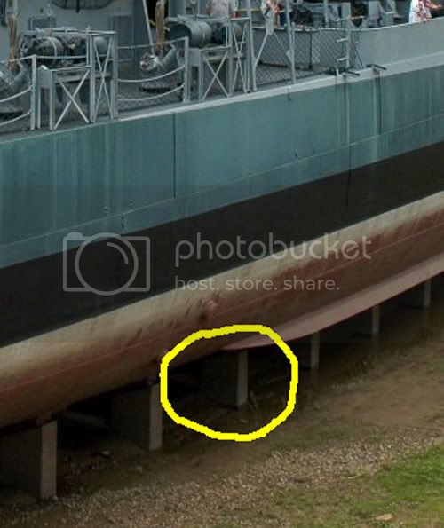
Photo of the port side with lightened area of port Fwd intake:


Photo of the area of the Stbd Aft Intake (back on underside below bilge keel):


Regards
Steve
TracyWhite
Visit this Community
Washington, United States
Joined: January 18, 2005
KitMaker: 527 posts
Model Shipwrights: 464 posts
Posted: Friday, February 06, 2009 - 06:33 AM UTC
Something else you could do is buy the plans from DestroyerHistory.org. I don't consider them to be expensive and the money goes to help support a great cause!
Hatter50
Visit this Community
North Carolina, United States
Joined: June 17, 2006
KitMaker: 478 posts
Model Shipwrights: 82 posts
Posted: Friday, February 06, 2009 - 07:26 AM UTC
Good call on that Tracy. I'm in the process of making contact now. That does look like a very GOOD disk. I already got the FD CD of plans and images..........great for above the waterline.

I guess it's cheaper than making a long distance trip to Baton Rouge to see the Kidd in person.

Regards
Hatter50
Visit this Community
North Carolina, United States
Joined: June 17, 2006
KitMaker: 478 posts
Model Shipwrights: 82 posts
Posted: Saturday, February 07, 2009 - 10:32 AM UTC
OK, I'll shut up now about the condenser intakes.

I finally "figured" out about the Condenser intakes, or scoops on the early Fletchers. I got a peek at some plans for the Fletcher and the photos of the USCGC Taney's intake is close. The Fletcher's has 2 splitter fins instead of the one in the Taney, is 20+ inches wide and 4'6" + long. They are located inboard of the propeller shaft centerline and just forward of thier respective engineroom. The intake pipe angles up and aft acting as a scoop when steaming ahead. I do not know if there is or was a screen attached.

Here is the Taney again.


The Taney website says there was a screen attached. I saw no notation on the Fletcher plan for a screen.

Regards
Steve
 _GOTOTOP