_GOTOBOTTOM
General Ship Modeling
Discuss modeling techniques, experiences, and ship modeling in general.
USS Carondelet. Civil War gunboat, 1/96th
Devin
Visit this Community
New Jersey, United States
Joined: January 18, 2005
KitMaker: 79 posts
Model Shipwrights: 45 posts
Posted: Monday, February 08, 2010 - 07:43 AM UTC
I'm working on my first scratch-build, about three weeks of real serious work on it down, and I wanted to start posting. The full information is on [u]My Site[/u] if you want to see it all. I'm not going to post everything I put on my site here and on other websites, it's just too much work.


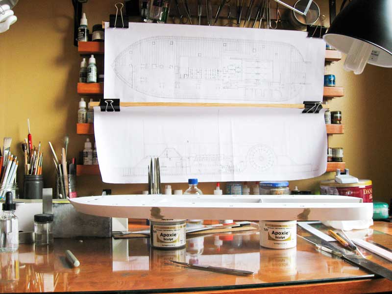
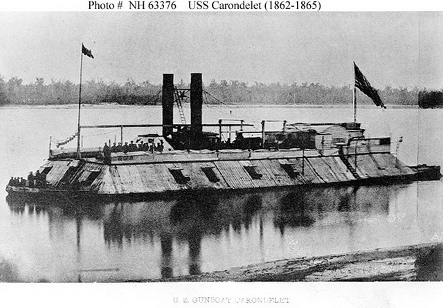
This build is of the USS Carondelet. For some specifics about the City Class gunboats, of which she was a member, and a bit of history on Carondelet, visit my website above. The build will be mostly of styrene, but I will use cast resin parts and brass where I can get away with it.

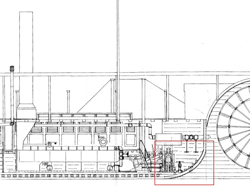
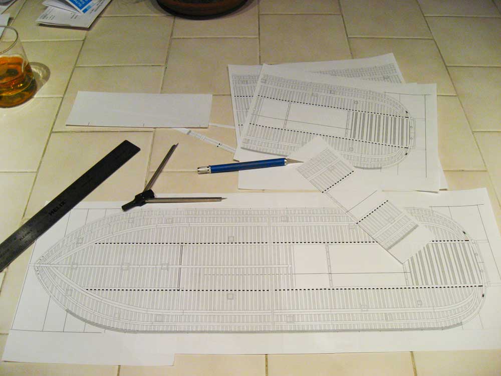
Anyway... first off is the overhead plan. I scanned the plans I'm using into Photoshop, sized them, printed them out, taped them together, and used contact adhesive to attach them to .060 sheet styrene (~1.5mm).


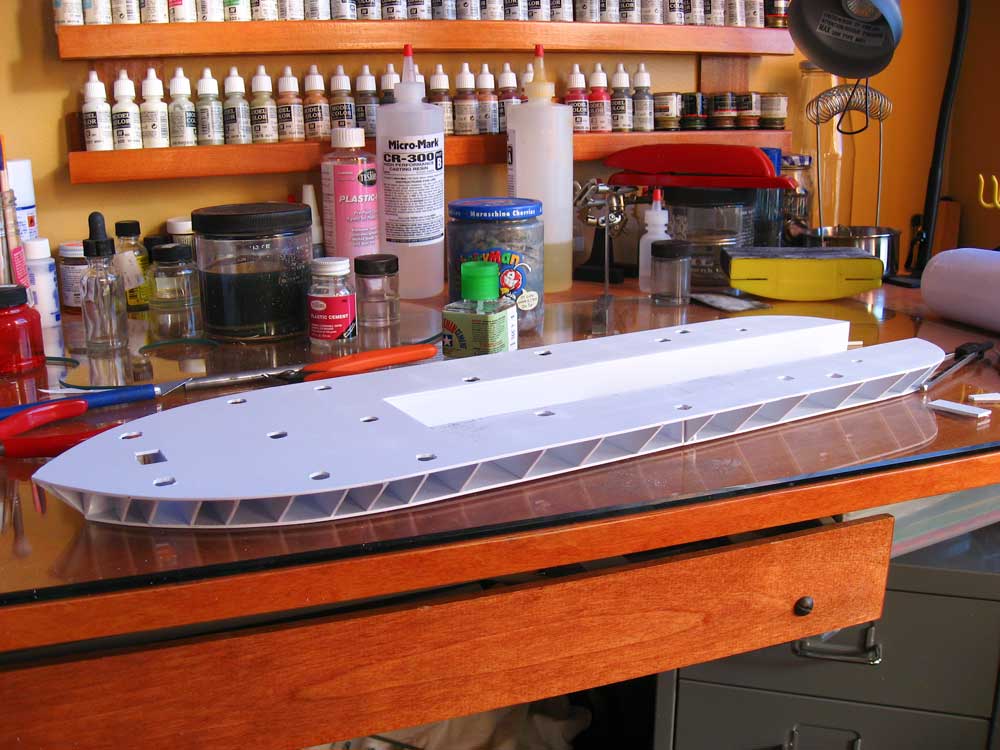
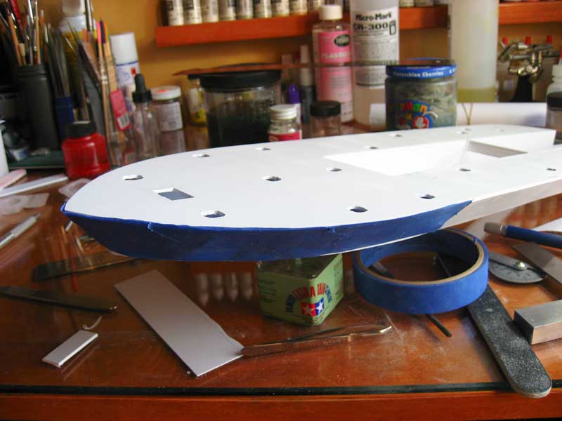
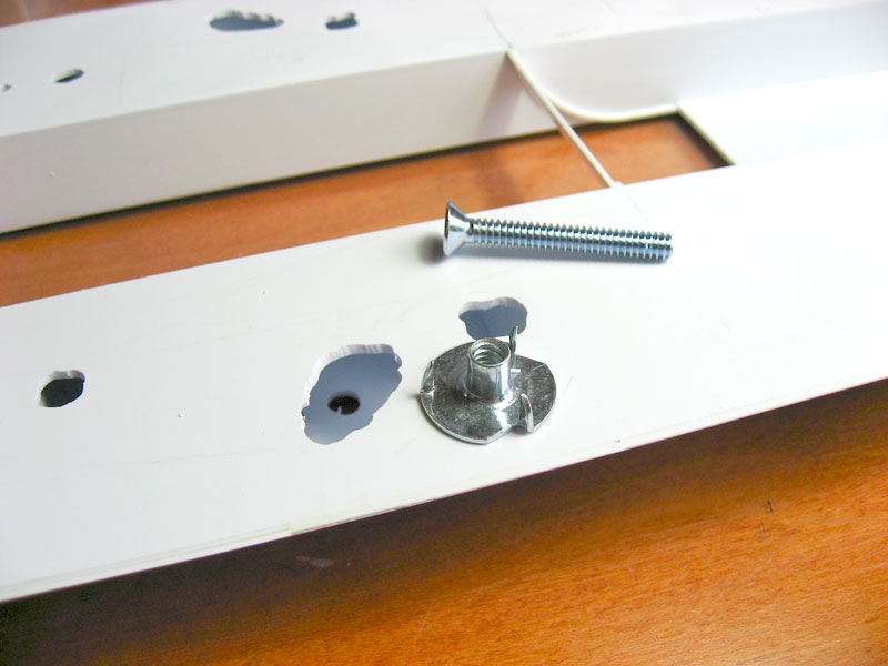
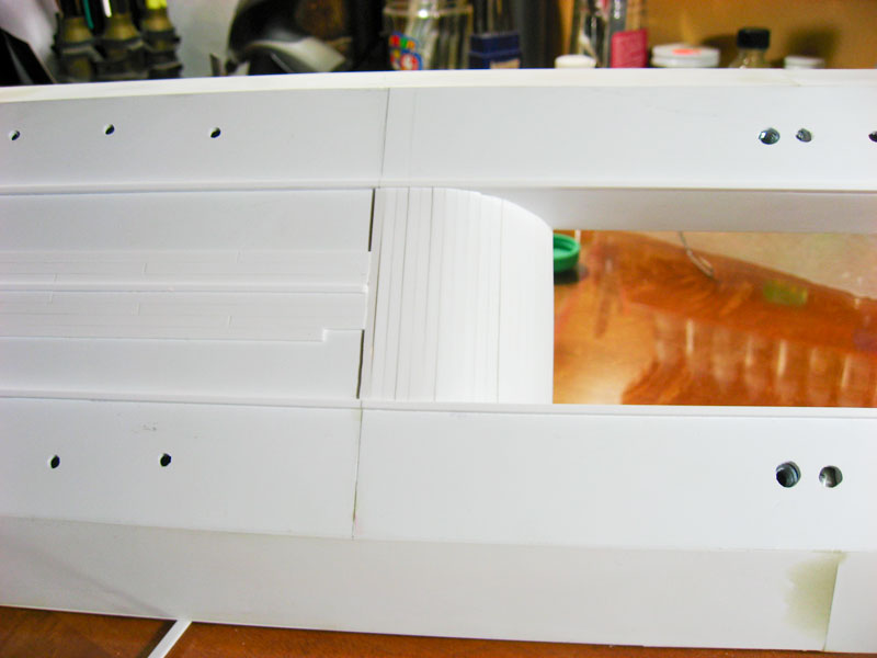
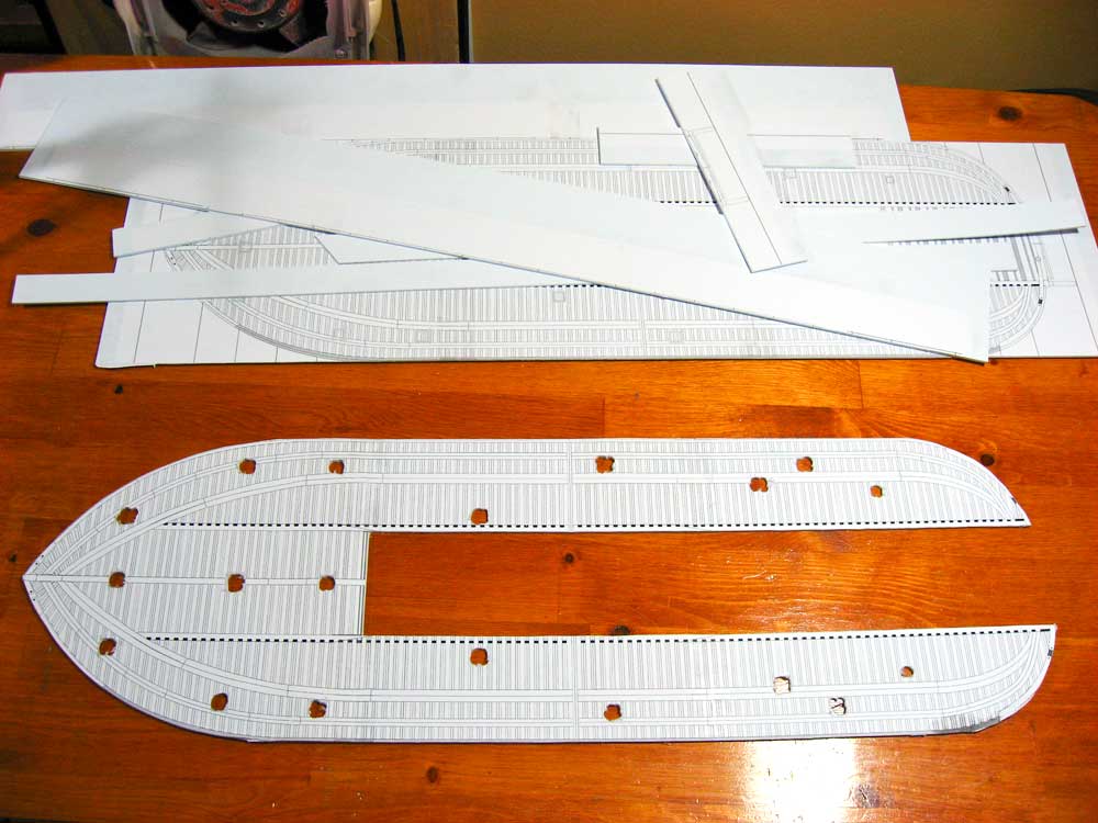
Next comes the cutting. Here's the main deck. The large channel down the middle of it is for the paddle wheel. These City Class boats were of a mid-wheel design, utilizing the casemate and hull thickness for protection of the wheel assembly. The holes drilled in the deck are for the passages down into the lower hull where they stored ammunition, ropes, stores, etc. I drilled them round here because it was easier then cutting square holes in such thick styrene. When I plank the decks these openings will be squared off.


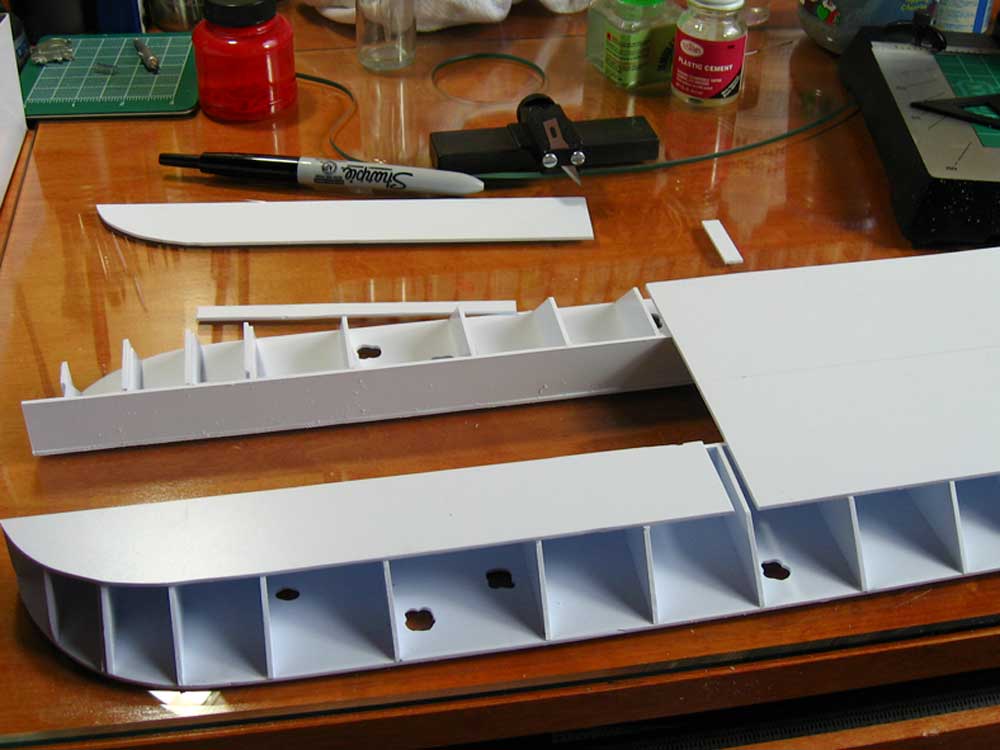
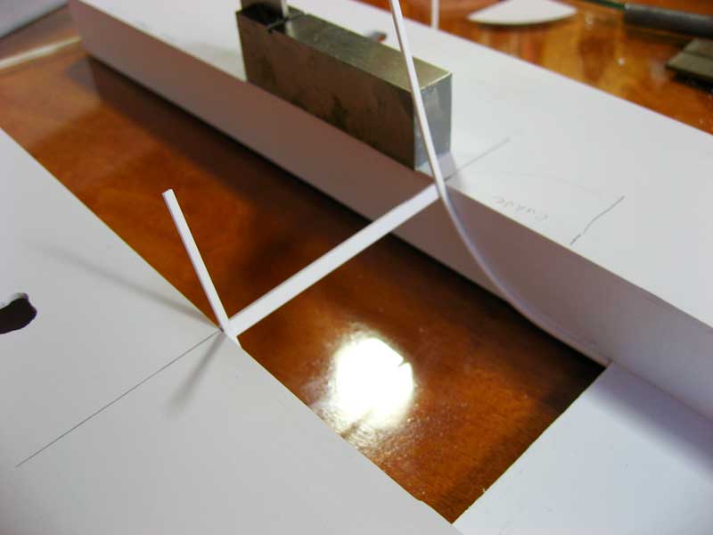
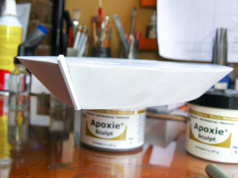
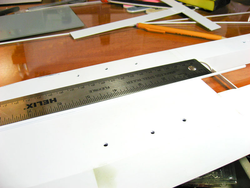
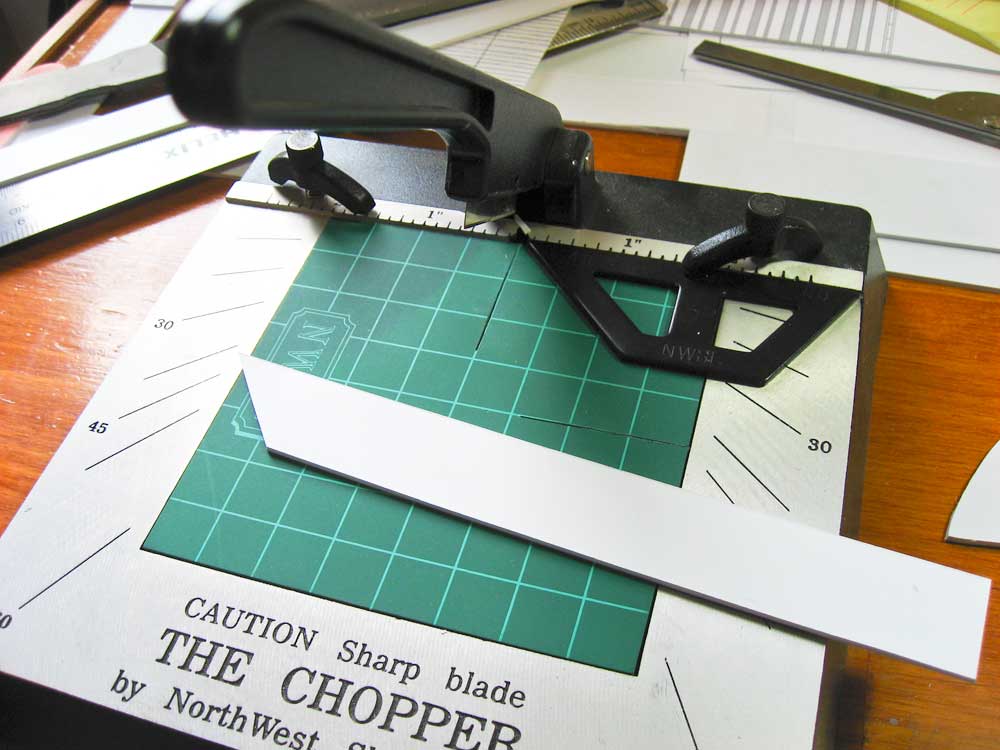
The City Class gunboats hull was completely parallel between the upper and lower levels. Measuring this distance and allowing for thickness of plastic, I came up with a frame height of 21mm. Fortunately, my strip wood/styrene cutter's maximum extension was exactly 21mm. Couldn't have planned it any better.


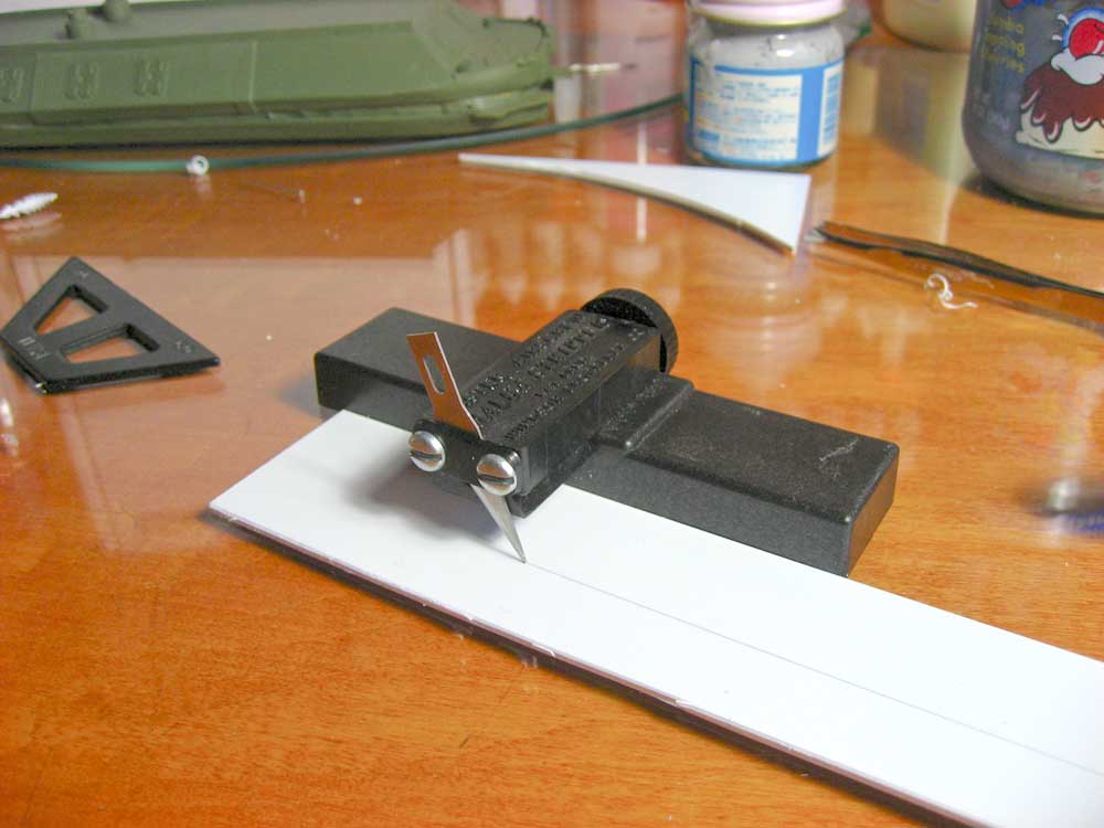
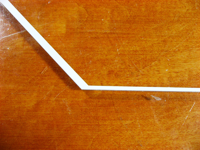
And continuing on the "that was easy!" track, MOST of the hull angles for the frames are 45-degrees. Out comes the chopper.


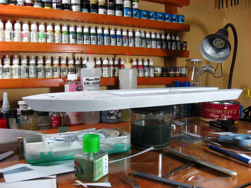
Everything cut to length and with the 45-degree angles cut, assembly was quick and straight-forward.


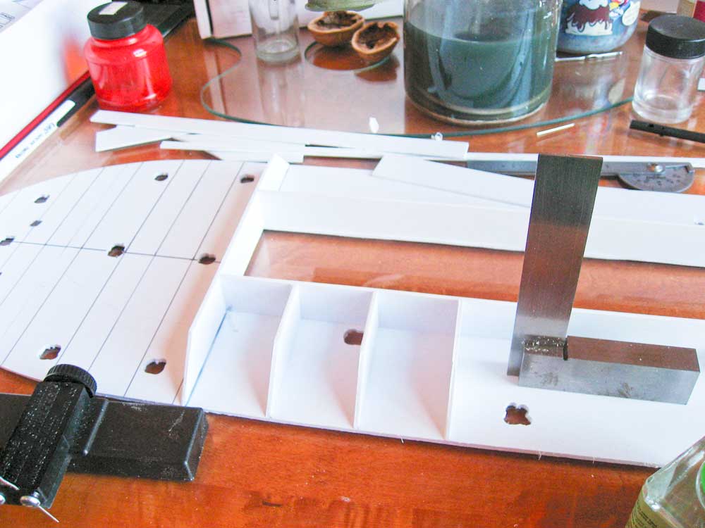
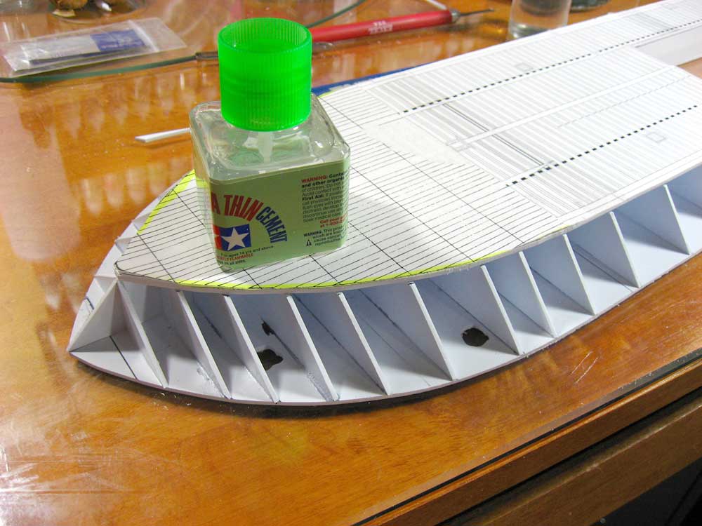
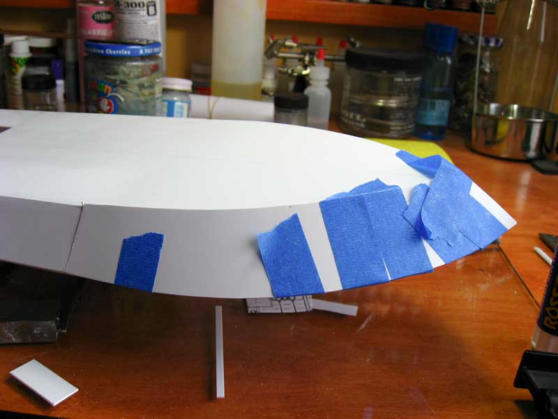
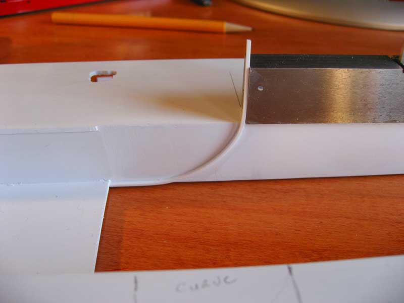
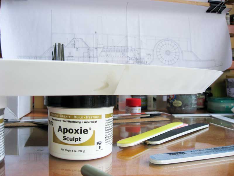
Until it came time add the lower part of the hull.


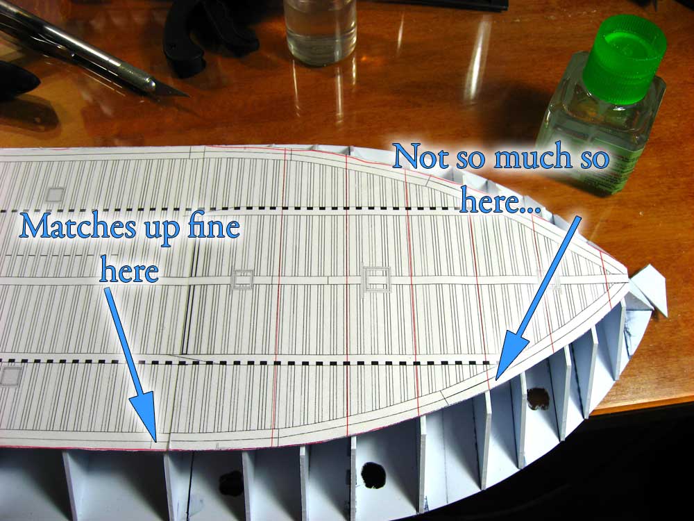
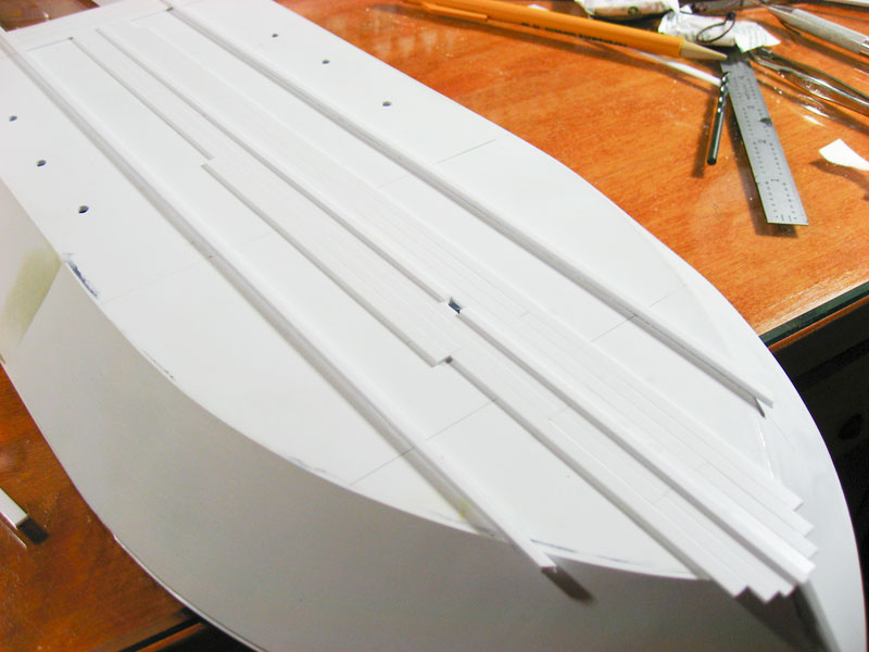
One of the sets of plans I had showed that EVERY angle on the hull was 45-degrees. As can be seen in the above image, that doesn't work out so well when you get to the forward and aft part of the hull. In retrospect I should have figured that out before hand, but oh well. I lost a few hours to marking the new frame angles, snapping off three of them aft and 8 of them forward, cutting them again, then attaching once more. Much better after all of that extra work:
Devin
Visit this Community
New Jersey, United States
Joined: January 18, 2005
KitMaker: 79 posts
Model Shipwrights: 45 posts
Posted: Monday, February 08, 2010 - 07:45 AM UTC
A couple more photos. After I made sure that the bow frames matched up nice and neat, I then noticed that the hull bottom at the stern matched up fine in width, but not length. I was able to fix this by the bottom and inserting spacers, along with a couple more frames to support the joints.


With that resolved and a little sanding to begin to shape the frames along the curves of the bow and stern, and a few extra stringers between the frames at the extreme curves for added stability, it's starting to look like a proper hull. At this point the bow-to-stern measurement of the hull is approximately 21" (53.5cm). The next step: sheet everything and then start framing out the casemate.
Grumpyoldman
Staff Member_ADVISOR
KITMAKER NETWORK
Visit this Community
Florida, United States
Joined: October 17, 2003
KitMaker: 15,338 posts
Model Shipwrights: 981 posts
Posted: Monday, February 08, 2010 - 09:57 AM UTC
Really nice work,
I hope you'll keep us posted on this project.
retiredbee2
Visit this Community
Florida, United States
Joined: May 04, 2008
KitMaker: 757 posts
Model Shipwrights: 29 posts
Posted: Monday, February 08, 2010 - 10:54 AM UTC
Nice job.....and your work table is so pristeen and neat. How do you do that ?...... ...Al
#027
Visit this Community
Louisiana, United States
Joined: April 13, 2005
KitMaker: 5,422 posts
Model Shipwrights: 5,079 posts
Posted: Monday, February 08, 2010 - 11:38 AM UTC
Wonderful work!
lone-ronin
Visit this Community
Mississippi, United States
Joined: January 31, 2006
KitMaker: 147 posts
Model Shipwrights: 16 posts
Posted: Monday, February 08, 2010 - 05:54 PM UTC
This looks like it is going to be an awesome build! I have always liked the Civil War ironclads, I just don't have the skill to build them. The Carondolet's sister ship, the Cairo (or what is left of her) is about 45 minutes from here.
treadhead1952
Visit this Community
Nevada, United States
Joined: June 12, 2008
KitMaker: 552 posts
Model Shipwrights: 493 posts
Posted: Tuesday, February 09, 2010 - 01:20 AM UTC
Excellent work on what promises to be a real eye catcher of a project.

After more than a couple scratch builds in lovely all white styrene under the bright lights of the work bench, I can appreciate the level of workmanship.
sacman
Visit this Community
Texas, United States
Joined: April 16, 2009
KitMaker: 16 posts
Model Shipwrights: 6 posts
Posted: Tuesday, February 09, 2010 - 02:56 AM UTC
Where do you get your plans from?
Devin
Visit this Community
New Jersey, United States
Joined: January 18, 2005
KitMaker: 79 posts
Model Shipwrights: 45 posts
Posted: Tuesday, February 09, 2010 - 04:03 AM UTC
Thanks for the comments, guys. It's funny how everyone comments on how clean my bench is; I think it's a little messy now myself, but it looks better than it did when I was chopping and sanding styrene. I have such a small amount of space to work in that I have to keep it uncluttered when working on a large ship. Thanks for the quality comments, I'm not sure how long that will last, but I picked a simple hull for my first attempt, so hopefully that will help me out.

My plans are from two sources. One set is CAD drawings that were posted on a now defunct Yahoo group about USS Cairo. I converted these to PDF and printed them out. They have at least one issue I'm aware of, though -- the issue that caused my frame mis-match error. I also have two sets of plans from David Meagher. David's been drawing ironclad plans by hand for over 20 years now. I have his 1/96th scale set of City Class plans from the early 90's (be aware, though, that the scale on those is a bit off, re-size them if you use them) and a 1/48th set that he is still working on. David sells his plans directly when he's in the country, or you can get his stuff from Taubman plans online. Look for the USS Cairo plans with DM in the stock number and that's his stuff. He does amazing work and has drawn nearly all of the ironclads from both sides of the war.

Ronin, I've always wanted to get down to see the Cairo. Not much call for me to travel in that area, though, and Vicksburg isn't the easiest place to get to! Speaking of how "what's left of her" is on display, don't read the book "Hardluck Ironclad" if you have a weak stomach. I know next to nothing about recovering shipwrecks, but reading that book even I could tell how they were going about Cairo's recovery all wrong.
lone-ronin
Visit this Community
Mississippi, United States
Joined: January 31, 2006
KitMaker: 147 posts
Model Shipwrights: 16 posts
Posted: Tuesday, February 09, 2010 - 05:13 AM UTC
Funny you should mention "Hardluck Ironclad", as that book is one of the things that got me interested in Ironclads. That and a story that National Geographic did eons ago about the Monitor wreck. I do wish they would try to raise the Baron de Kalb...
Devin
Visit this Community
New Jersey, United States
Joined: January 18, 2005
KitMaker: 79 posts
Model Shipwrights: 45 posts
Posted: Tuesday, February 09, 2010 - 05:24 AM UTC
Do they know De Kalb's location? I know that Clive Cussler found Carondelet's location about 48 hours AFTER a dredge boat destroyed her on the bottom of the Ohio river.

As far as ironclads go, I really wish someone would raise the USS Tecumseh. She's in shallow water and nearly perfect condition according to the surveys.
Halfyank
Visit this Community
Colorado, United States
Joined: February 01, 2003
KitMaker: 5,221 posts
Model Shipwrights: 1,821 posts
Posted: Tuesday, February 09, 2010 - 06:14 AM UTC
Really nice work Devin. Seeing your well ordered workbench, well compared to mine anyway, I can see how you do such neat work.

You guys beat me to mentioning "Hard Luck Ironclad." I picked it up used from a library sale a while back. It's certainly interesting reading. I didn't know about the destruction of the Carondelet, truly a shame.

I really, really mean to visit some of these historic sites east of the Mississippi one day before I die.
lone-ronin
Visit this Community
Mississippi, United States
Joined: January 31, 2006
KitMaker: 147 posts
Model Shipwrights: 16 posts
Posted: Tuesday, February 09, 2010 - 06:44 AM UTC
De Kalb is in the Yazoo River near Yazoo City, MS. As i understand it, her location is known, and I had heard talk at one time of a proposal to build a coffer dam around her and filling it with clear water so that she would be in sort of an "underwater museum". This was years ago, and I have not heard anything else about it. I think the Tecumseh would be another good candidate for raising.
lone-ronin
Visit this Community
Mississippi, United States
Joined: January 31, 2006
KitMaker: 147 posts
Model Shipwrights: 16 posts
Posted: Tuesday, February 09, 2010 - 06:51 AM UTC
You may have seen this, but this Park Service report has some drawings of Cairo that might be useful.

http://www.nps.gov/history/history/online_books/vick/cairo_hsr.pdf
Devin
Visit this Community
New Jersey, United States
Joined: January 18, 2005
KitMaker: 79 posts
Model Shipwrights: 45 posts
Posted: Tuesday, February 09, 2010 - 10:00 AM UTC
Ah, I have scans and clips from that PDF here and there, but have never seen the entire document. Thanks! Good detail shots. I plan on doing some building of the furnace and boilers, and the paddle wheel. I'm not sure about the engines and arms; I'm going to cut-away part of the casemate on the starboard side to show the gundeck and other details, but honestly I'd like to avoid that much work on the engines and pittman arms if possible.

I often wondered why they didn't try the coffer dam idea around Tecumseh. They'd have to flip her over so she's vertical, but it'd still be easier than righting her.

There's a lot of information on the ironclads that Numa found here:
http://www.numa.net/expeditions.html
CaptSonghouse
Visit this Community
California, United States
Joined: August 08, 2008
KitMaker: 1,274 posts
Model Shipwrights: 1,236 posts
Posted: Tuesday, February 09, 2010 - 12:12 PM UTC
Hi Devin!

As a fellow scratchbuilder, it's perversely gratfying to see I'm not the only one to have fit problems --that's why I often use the trim-to-fit method instead of pre-cutting where possible.

Your subject matter is wonderful and look forward to seeing her advance to completion.

--Karl
TANKER-NEIL
Visit this Community
England - East Midlands, United Kingdom
Joined: March 09, 2009
KitMaker: 13 posts
Model Shipwrights: 4 posts
Posted: Friday, February 12, 2010 - 08:40 AM UTC
luv ironclads yours looks abit special will follow the project with interest keep up the good work
JMartine
Visit this Community
New Jersey, United States
Joined: October 18, 2007
KitMaker: 1,698 posts
Model Shipwrights: 1,514 posts
Posted: Saturday, February 13, 2010 - 07:35 AM UTC
Great skills, very nice build, interesting subject. A winning WIP for sure, thanks for sharing!
Devin
Visit this Community
New Jersey, United States
Joined: January 18, 2005
KitMaker: 79 posts
Model Shipwrights: 45 posts
Posted: Sunday, February 21, 2010 - 02:24 PM UTC
Thanks for the feedback everyone. Here's my progress as of today.

With the hull bottom, main deck, and all the frames stuck together, it's time to sheet. Along the hull sides where everything's nice and straight, I simply glued in .030 styrene and trimmed to shape. For the curves forward and aft, though, I "plated" the areas with blue masking tape, trimmed it, then stuck it to sheet styrene and cut it roughly to shape with shears.


It was then glued to the hull and trimmed and sanded after the glue and styrene had dried.


One of the few curves on a City Class gunboat is on the bottom of the hull, where the flat bottom hull transitions into the paddle wheel well. This is illustrated here, boxed in red, on the David Meagher plans.


I transferred this curve to the inside of the hull trough by cutting the curve out of a copy of the plans, taping it to both sides, and tracing it with a pencil. I then affixed one end of a strip of styrene to the lower hull's end in the trough, let that dry, and then gently curved the styrene to follow the pencil mark, careful to make sure that the ends of the strips on both sides broke the surface of the main deck at the exact same point.


Here I show one plank installed, before the curved sections were cut flush with the deck, to make sure everything lined up. Eventually the entire curve will be planked with strips of styrene like this. I need to allow for steam exhaust piping, however, and I'd rather wait until the boilers and piping go in so I can cut the planks before attaching, rather than doing a retro-fit.


This is how she sets now. At this point I'm filling gaps with styrene and using my rasp file and sandpaper to make sure everything is straight. I don't have to be too concerned with neatness at this point, as everything shown will be planked with another coat of styrene, but I still find myself obsessing over little things. That's half the fun of it, I suppose.

TAFFY3
Visit this Community
New York, United States
Joined: January 21, 2008
KitMaker: 2,531 posts
Model Shipwrights: 1,244 posts
Posted: Monday, February 22, 2010 - 01:57 AM UTC
Hello Devin, I'm following this thread with great interest. I've always liked and wanted to model the Carondelet. I first read about her when I was a youngster in a book I got from the A&P supermarket. I had considered a scratch build like yours and am now inspired once again to give it a try. I've already gotten a few ideas from you on how to solve some of the problems. I never thought of using masking tape to make a template. I am looking forward to seeing more of your work and the completion of this historic ship. Al
Devin
Visit this Community
New Jersey, United States
Joined: January 18, 2005
KitMaker: 79 posts
Model Shipwrights: 45 posts
Posted: Tuesday, February 23, 2010 - 03:55 AM UTC
Al, Thanks. There's still a few things I need to figure out as I go along, such as how the best way to build and attach the casemate while still leaving it open enough to detail the interior, what materials to use for the paddle wheel, where the rudder control ropes run, etc., but it's a run process. The hull really is simple to build, though.
Devin
Visit this Community
New Jersey, United States
Joined: January 18, 2005
KitMaker: 79 posts
Model Shipwrights: 45 posts
Posted: Thursday, March 25, 2010 - 08:34 AM UTC
Not a lot of progress due to travel and writing, but I wanted to put up something since it's been over a month. Above I stated how I don't have to be too concerned with neatness at this point, as this skin over the hull is the first of two. I do, however, want to fill any major dips so that the planking doesn't run too wonky. Enter Aves Apoxie Sculpt. This is much like your basic two-part putty. I use it almost exclusively. It's more time intensive than something like hobby putty or Bondo as it must be mixed and it takes a day to dry. The benefits are that there is no shrinkage when dry -- absolutely zero -- and if you use it to build up an area you can then sand an edge down until it's a razor sharp edge, or as a filler it will feather out until it's translucent. You can roll it into a tube, let it dry, and work it in a lathe. I've never seen a putty that works as well or is as versatile as this stuff.


Here you can see where I have applied the Aves to the hull. When I sheeted the hull I started with the straight runs amidships and fit them between the two decks. When sheeted forward and aft, though, I put the sheeting on the outside of the deck radius. Not a big difference, but it's a better bond, and I ended up with a step-down in in those areas.

*Note my cool make-shift holders for rolled plans!*


This is it sanded smooth -- mostly, I put a little dab more in a gouge that I made while sanding -- and you can see how it feathers down to almost nothing when sanded. I don't want a lot of it on the styrene for this purpose as I want as much of a styrene-to-styrene bond between this layer and the next as possible.


Another bit of work as to do with starting the keel. This is something that had I thought it out further before I started then I would have made this an actual structural keel going from the bow to the fore end of the engine room, but I didn't, so live and learn. When I sheeted the bow area I left a gap and then fit this piece of rectangular styrene stock. I used a lot of plastic cement and my machinists squares to make sure it's all true and straight. The gaps along the side will be covered by the fitted planking in the next pass.


Now I'm waiting for the rest of the Aves putty to dry, sand that out, then I get to extend that keel on the bow to the lower hull and start planking the bottom of the hull.
Devin
Visit this Community
New Jersey, United States
Joined: January 18, 2005
KitMaker: 79 posts
Model Shipwrights: 45 posts
Posted: Sunday, May 09, 2010 - 02:09 PM UTC
I finally got some time off (my first free weekend in nearly a month). So, an update:

Had to do some damage control. I realized that I hadn't fixed any bolts inside the hull to mount it to the base. I opened up a couple of the holes in the deck and put them inside, positioned them with a paint brush handle, tacked them in place with super glue, then packed epoxy putty around them to get a solid join.


Here's the curve between the lower and upper hull that I showed started a few posts ago. Now I've finished planking the curve.


The City Class had three keels. Here's the centerline keel with the upturn for the bow. Nice, simple 45-degree angle here.


Here's the rear end of that centerline keel, attached to the hull. I had to rip this piece out once as it was WAY off of the center line. Working backwards I found a measurement here and there off by only a millimeter or two which added up the problem. A lot of sanding and swearing and re-measuring fixed the issue.


Here's where I sit now. The three keels are clearly visible here. I've started planking the lower hull. I'm using Evergreen strip styrene, 3mm wide by 1mm thick, cut into 103mm lengths. It's slow, tedious, yet rewarding work. I'm leaving the keels and the planks proud of the hull edge for now so that I can trim and sand them all at the same time for a uniform finish.


That's it for now.
JMartine
Visit this Community
New Jersey, United States
Joined: October 18, 2007
KitMaker: 1,698 posts
Model Shipwrights: 1,514 posts
Posted: Thursday, May 13, 2010 - 12:34 AM UTC
great update Devin, look forward to the rest!
lone-ronin
Visit this Community
Mississippi, United States
Joined: January 31, 2006
KitMaker: 147 posts
Model Shipwrights: 16 posts
Posted: Thursday, May 13, 2010 - 02:35 AM UTC
Looking good!
 _GOTOTOP