

 Al
Al

Go to modelshipwrights.com for the current dynamic site!
General Ship Modeling
Discuss modeling techniques, experiences, and ship modeling in general.
Discuss modeling techniques, experiences, and ship modeling in general.
Hosted by Jim Starkweather
Bronco 1/35 Seehund

TAFFY3

Joined: January 21, 2008
KitMaker: 2,531 posts
Model Shipwrights: 1,244 posts

Posted: Friday, July 02, 2010 - 02:00 AM UTC
Hello All, I just received my SEEHUND and upon opening the box was quite happy with what I saw. There are four sprue's, the instruction sheet, a small photo-etch sheet, a base, a small clear sprue, and a color sheet with paint schemes for four different boats. Two are dark gray, one of which has white spots on the upper surfaces, and two are in an overall light gray scheme. There are some markings on the decal sheet that are not shown on the four schemes provided. I assume they are for another boat, or boats, not shown. There is also a page containing corrections for page three of the instruction sheet. The photo-etch sheet contains just nine parts, one of which is a name plate for the base. The other eight pieces are vanes that go around the head of each torpedo. There are small notches molded in part B1 for these vanes which will help align them. The torpedoes are quite detailed and molded with separate warheads and detonators which will make painting them easier. There are also three different color schemes for the torpedoes. This adds some variety to your modeling options. The parts are molded in a light gray plastic, with the base molded in black. Some of the parts are delicate and will require some care removing them from the sprue. The parts count is quite low, making this look like a fairly quick and easy build. I can't comment on the fit as of yet but judging by the only other Bronco kit I have worked on it should be good. I am quite pleased by what I have seen so far and I am looking forward to starting this kit and will post some pictures when I do. Al
AlTAFFY3
Joined: January 21, 2008
KitMaker: 2,531 posts
Model Shipwrights: 1,244 posts
Posted: Saturday, July 03, 2010 - 03:31 AM UTC
Hello, I started working on the Seehund today. The main hull halves went together well with no need for filler, just some careful sanding. You have to open some holes before joining the hull together, which ones depends on the version you are building. The rudder doesn't have to be trapped between the halves, it can be added after the hull is completed. You must be careful because some of the parts are extremely delicate. I broke off one of the handles near the bow and had to replace it with brass rod. I also broke one of the hinges on the hatchway, twice! I managed to find it, twice, and re-attach it, twice, so far. The dive planes are meant to be movable, but they have a very weak shaft on one plane and a tiny stub on the other. It would be impossible to attach them to each other, and if you did the joint would be extremely fragile. I cut off the shaft and stub and drilled a hole in each plane and used a piece of brass rod. It gave me a much stronger joint and allows me to position the planes as desired. I am not going to use the kit provided stand. So, I drilled two holes in the keel and inserted some plastic tubing. I sanded it flush with the keel. The tubing will slip over some brass rod on the finished base, but it will also allow me to mount the model on a temporary base while I am working on it. Well that's all for now, I will post some more as I progress. Al
AlTAFFY3
Joined: January 21, 2008
KitMaker: 2,531 posts
Model Shipwrights: 1,244 posts
Posted: Monday, July 05, 2010 - 05:51 AM UTC
Hello again, I did some more work on the Seehund today. I'm doing the Type XXVIIB, without the saddle tanks. The only other difference is at the stern, most notably the rudder. Two rudders are provided, one is straight (Type XXVIIB5), and the other has a circular shroud which surrounds the propeller (Type XXVIIB). There are also two different cone shaped parts to mount on the stern, depending on which type you are building. Part A24 is shorter and is used for the XXVIIB5, the longer part A23 is used for the XXVIIB. On the correction sheet for step three you are shown which holes to open for the different rudders. The propeller had some fine flash on one blade and needed careful cleaning of the sprue attachment points. I previously mentioned that the rudder could be added after the hull was assembled. This is true of the Type XXVIIB only. The straight rudder for the Type XXVIIB5 must be installed before gluing the hull together. The ducted rudder can be carefully installed after attaching the propeller. The periscope consists of two parts , A26 and a flange, B16.I didn't think the assembly was strong enough so I drilled a hole in the 'scope, flange, and through the conning tower decking into the hull. I then glued a piece of brass wire into the 'scope, making it long enough to go through the conning tower decking and into the hull. I slipped the flange (B16) over the wire and glued it to the 'scope. I can now add the 'scope after assembling the conning tower to the hull. The wire also makes a convenient handle for painting. I did the same for part A25 and a second part B16. This assembly mounts to the hull aft of the hatchway. It fits through a hole in the conning tower roof. I don't know what it is on the real sub, maybe someone else does? Aft of that is an assembly consisting of parts A9, A10,A19, A21, and A22. I think this is the intake for the diesel engine on the real boat. Part A19 looks like the float used to close a valve (like in a toilet tank) when submerging. I would like to know for sure, if anyone has better information. I replaced part A10 with a similar length of plastic tube and once again used brass wire to reinforce the assembly. This assembly is attached to the hull and the top fits into a hole in the conning tower roof. It looks good but unless you leave the conning tower removable it will be invisible. Finally I attached part A13 in a hole near the bow, and also the torpedo supports, parts B17, to the sides of the hull. Thats all I've done so far, I will keep you posted when I make some more progress. Al
MrMox

Joined: July 18, 2003
KitMaker: 3,377 posts
Model Shipwrights: 985 posts

Posted: Monday, July 05, 2010 - 06:08 AM UTC
We want pictures 
I have seen some pictures Showing some welded on "stops" for the rudder to control the movement - you might want to ad this detail.
Cheers/Jan
I have seen some pictures Showing some welded on "stops" for the rudder to control the movement - you might want to ad this detail.
Cheers/Jan

TAFFY3
Joined: January 21, 2008
KitMaker: 2,531 posts
Model Shipwrights: 1,244 posts
Posted: Monday, July 05, 2010 - 11:11 AM UTC
Quoted Text
Hello Jan, I saw your build and review right after I started this one. Very nice job, I was drawn to the scheme for the same boat that you did because of the colorful markings. But I think I like the Dark Gray with the White Spots scheme better. My camera has gone MIA, so I have to rely on my son for pictures. He is away, but when he returns I'll see what I can do. Could you post a picture of those rudder stops you mentioned? I'd like to see what they look like. We want pictures
I have seen some pictures Showing some welded on "stops" for the rudder to control the movement - you might want to ad this detail.
Cheers/Jan
AlTAFFY3
Joined: January 21, 2008
KitMaker: 2,531 posts
Model Shipwrights: 1,244 posts
Posted: Tuesday, July 06, 2010 - 07:28 AM UTC
Hello once again, I started working on the torpedoes and they are models unto themselves. The main body halves fit well with no filler required, just some careful sanding. There are three inspection covers and two small parts that are molded separately. They are located on the seam line and would have greatly complicated sanding it. Kudos to Bronco for making this assembly a little easier. The four fins were added next. They do require careful alignment. I have been using 'Gorilla' brand super glue gel for this build. I am very satisfied with the results. It bonds quickly and gives a strong joint. It made attaching small parts much easier. I reinforced the fins with Tenax after attaching them with the Gorilla glue. I am keeping the warheads separate for now to facilitate painting. I did glue the detonators (part B1) to the warheads, but did not add the arming propeller (part B8) or the four photo etched vanes to each detonator yet. The torpedo propellers were the most difficult part of the assembly. They require careful alignment of two blades to each of the two contra-rotating propellers for each torpedo. The blades look similar but they are different, they are numbered B5 & B7. It wasn't as hard as I feared thanks to the Gorilla glue. I'm not trying to sound like a commercial but I really like this glue. I drilled a hole in the inner propeller (part B10) and glued in a length of brass wire before adding the blades. I glued the blades to both propellers and then glued them together. The wire gives me a handle to hold while painting the propellers. I won't mount the props to the torpedoes 'til after painting. That's as far as I've gotten so far, to be continued.... Al
AlMrMox
Joined: July 18, 2003
KitMaker: 3,377 posts
Model Shipwrights: 985 posts
Posted: Wednesday, July 07, 2010 - 10:19 PM UTC
Hi Al, sorry for not getting back before now, but I have been very busy doing nothing (on vacation  )
)
Theres a bunch of very nive pictures here:http://www.schiffsbilderarchiv.de/seehund.htm showing the boat close up. Be carefull, I think the front is rebuilded on this one.
Heres a closeup of the rudder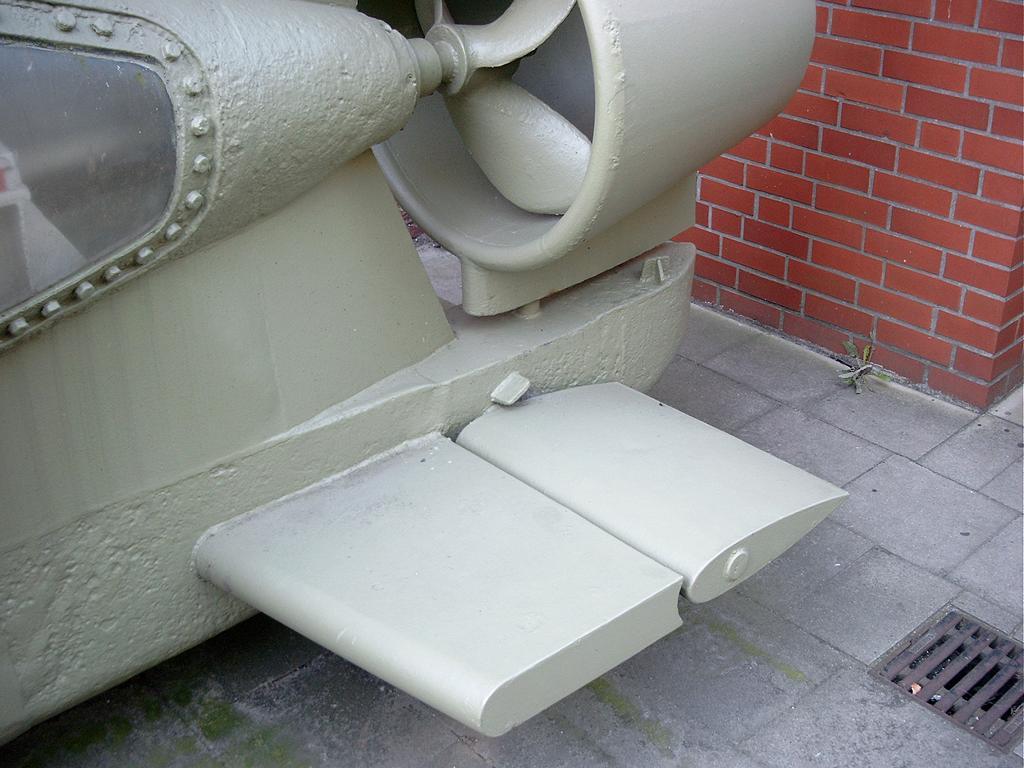
Cheers/Jan
)Theres a bunch of very nive pictures here:http://www.schiffsbilderarchiv.de/seehund.htm showing the boat close up. Be carefull, I think the front is rebuilded on this one.
Heres a closeup of the rudder
Cheers/Jan
TAFFY3
Joined: January 21, 2008
KitMaker: 2,531 posts
Model Shipwrights: 1,244 posts
Posted: Thursday, July 08, 2010 - 10:51 AM UTC
Thanks very much Jan, for the photo and the link, I will be adding those stops to my boat. There is one shown above the diving plane, I wonder if there is one below it as well? I would think there would be. Al
Al
dioman13
Joined: August 19, 2007
KitMaker: 2,184 posts
Model Shipwrights: 204 posts

Posted: Friday, July 09, 2010 - 05:41 AM UTC
Poor excuse for no pics Al. I wont tell your wife you swapped it for the sub  .
.
. TAFFY3
Joined: January 21, 2008
KitMaker: 2,531 posts
Model Shipwrights: 1,244 posts
Posted: Friday, July 09, 2010 - 07:23 AM UTC
You know Bob, If you told her what I really swapped it for, she'd probably be in jail for assault! Al
AlTAFFY3
Joined: January 21, 2008
KitMaker: 2,531 posts
Model Shipwrights: 1,244 posts
Posted: Saturday, July 10, 2010 - 05:13 AM UTC
Well, The majority of the assembly work is done. The only things left are the two gizmos that I believe are the torpedo release mechanisms. They are the smallest and most delicate parts in the kit. I painted the inside of the conning tower and the area around the hatch trunk, and then glued the conning tower to the hull. I used some small plastic shims between the vent holes, under the triangular projection at the front of the tower to improve the fit. This was the only place I saw any gap during test fitting, and it might have been because of something I did. I was also able to get a coat of paint on the torpedo bodies, the warheads, and the propellers. Still working on getting some pictures posted. Al
AlTAFFY3
Joined: January 21, 2008
KitMaker: 2,531 posts
Model Shipwrights: 1,244 posts
Posted: Monday, July 12, 2010 - 06:56 AM UTC
Hello once more, I painted the hull yesterday using Testor's Model Master Panzer Gray in a rattle can. I used a black pin wash and then dry brushed it with MM Acryl Euro I Gray and Schwarzgrau to break up the monotone Panzer Gray. Unfortunately I developed a severe case of fumble fingers and dropped the painted hull. The fragile tow ring on the extreme bow was destroyed. To repair the damage I cut a square notch, removing the damaged area, drilled a hole in a piece of plastic the thickness of the prow, cut a square section (surrounding the drilled hole) slightly larger than the notch, and then super-glued the replacement piece into position. Then I sanded the restored section to the right profile and thickness to match the rest of the prow. I masked off the repaired area and then repainted. Much to my relief it was a lot easier to repair the damage than I had feared. I think I'll quit while I'm ahead for now. Al
AlTAFFY3
Joined: January 21, 2008
KitMaker: 2,531 posts
Model Shipwrights: 1,244 posts
Posted: Wednesday, July 14, 2010 - 01:00 AM UTC
Well I started decaling today. One of the markings provided by Bronco, but not identified, is an 'elephant'. I found out it was the insignia for U-5052. Unable to find any information on this boat, I decided to make an educated guess. In the few war time photos I saw, it seemed a lot of the boats were painted a Dark Gray. Liking this better than the Light Gray scheme, I went with it. I used the 'elefant' and the number '52' on the conning tower. It appeared to me that they often used only the last two digits of a boat's number. This is all conjecture on my part, but seems reasonable. I also used the draft markings on the bow, amidships, and on the rudder. For the last one you have to separate the topmost white draft line from the decal and apply it to the hull directly above the rudder. The decals went down fine with a little help from Micro-sol to settle them over the rivets. I also put together the torpedo release mechanisms. They consisted of some small and very delicate parts and were a little 'fiddly' to assemble. The instructions show the starboard one correctly mounted to the hull, but show the portside one reversed. Jan Klarbaek mentioned this in his build and review so I knew to look out for it, thanks Jan. I thought it would be easier to paint them separately before attaching them to the hull. Still no pictures I'm afraid, but I hope to have some of the finished model at least. Al
AlTAFFY3
Joined: January 21, 2008
KitMaker: 2,531 posts
Model Shipwrights: 1,244 posts
Posted: Tuesday, July 27, 2010 - 11:49 AM UTC
The Seehund is now finished and armed. The boat is painted, has decals, and is weathered. I did not weather it very heavily. The boats were introduced late in the war and did not see as much action as other U-boat types. The torpedoes are models unto themselves and look great. They are almost as long as the sub itself. The only thing I added to my boat was a pair of grab handles on top of the conning tower, located on either side of the hatch. They appear in several period photos. I used some artistic license for the markings scheme I chose. Included on the decal sheet is an 'elephant'. It isn't identified among the markings and paint schemes on the kit supplied sheet. According to a website it was the insignia of U-5052. I decided to use it and the number '52' on the side of the conning tower. In many of the photos I saw, there is only a two-digit number displayed. This scheme of a dark gray hull and these markings is pure supposition on my part. But the artist in me liked the way it looks. To man my boat I ordered two figures made by u-models of France. They could be used on either a U-boat or a S-boote. This company has several 1/35 naval figures, including German, Italian, British, and US, as well as many naval accessories. I had used their depth charges on my PT boat, and was impressed by the quality. Al
Al |

WEB HOSTING BY


Copyright ©2021 Model Shipwrights and Kitmaker Network, a subsidiary of Silver Star Enterprises
All Rights Reserved. Please read our Conditions of Use and Privacy Policy.
All Rights Reserved. Please read our Conditions of Use and Privacy Policy.