Italeri have a 20mm horse drawn Breda

I'm using on for the back of my LRDG Chevy
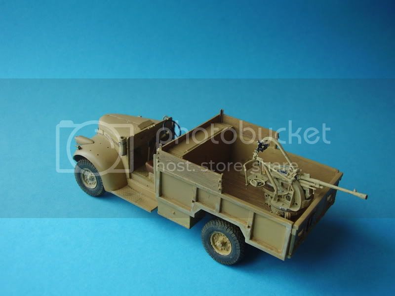
Nice little kit.
BTW do you have any other references for the fore and aft cabins? I have a mind to add some more basic detail below .
Thanks
Alan


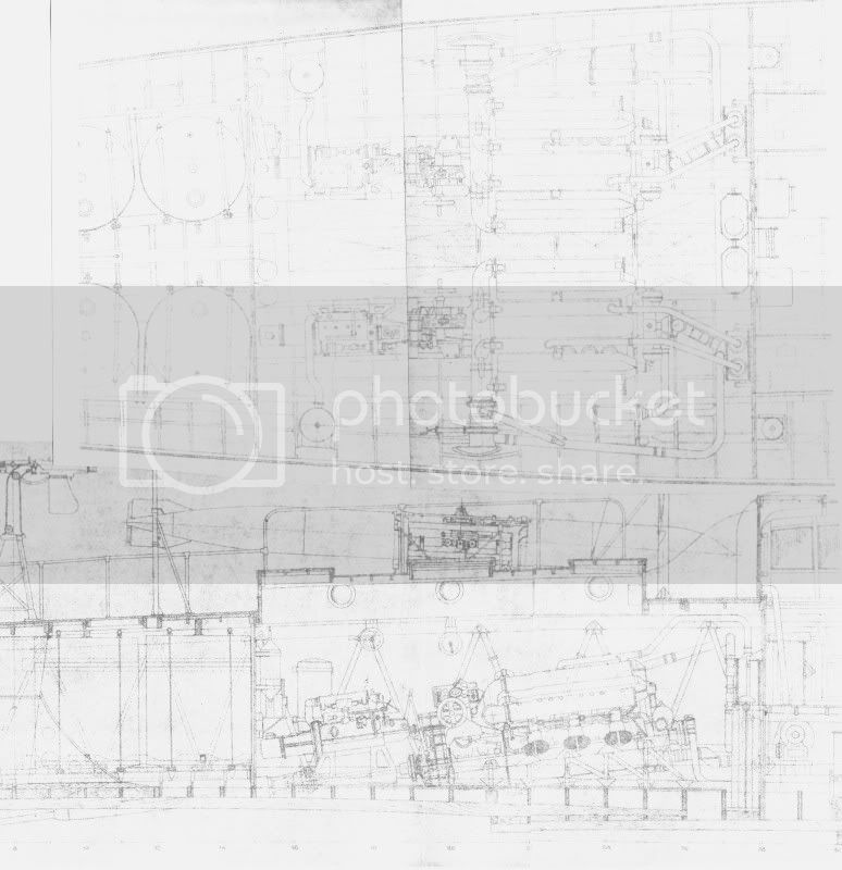


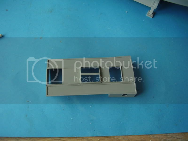
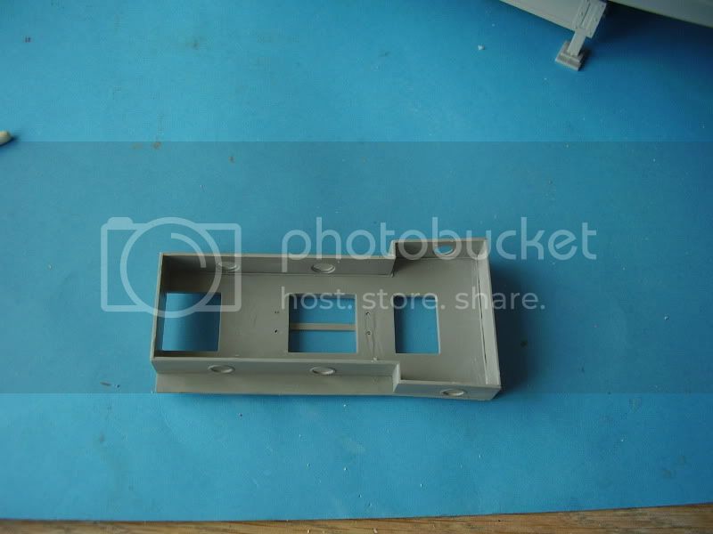
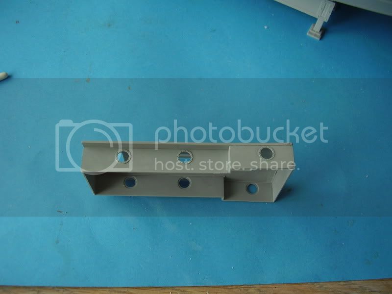

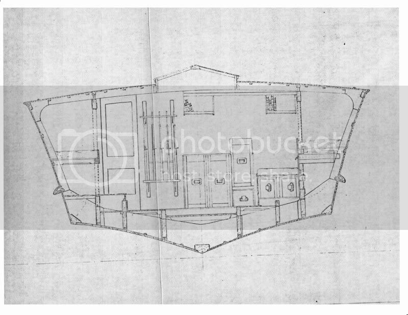
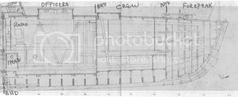
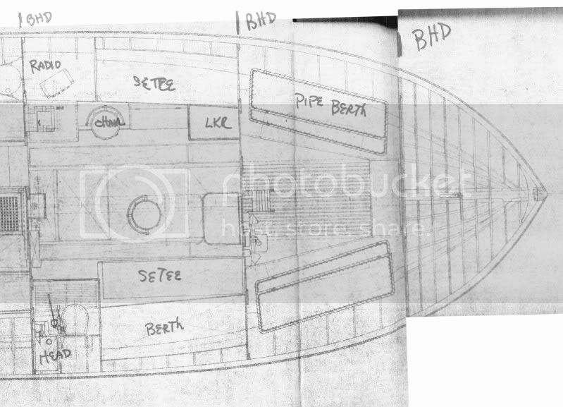
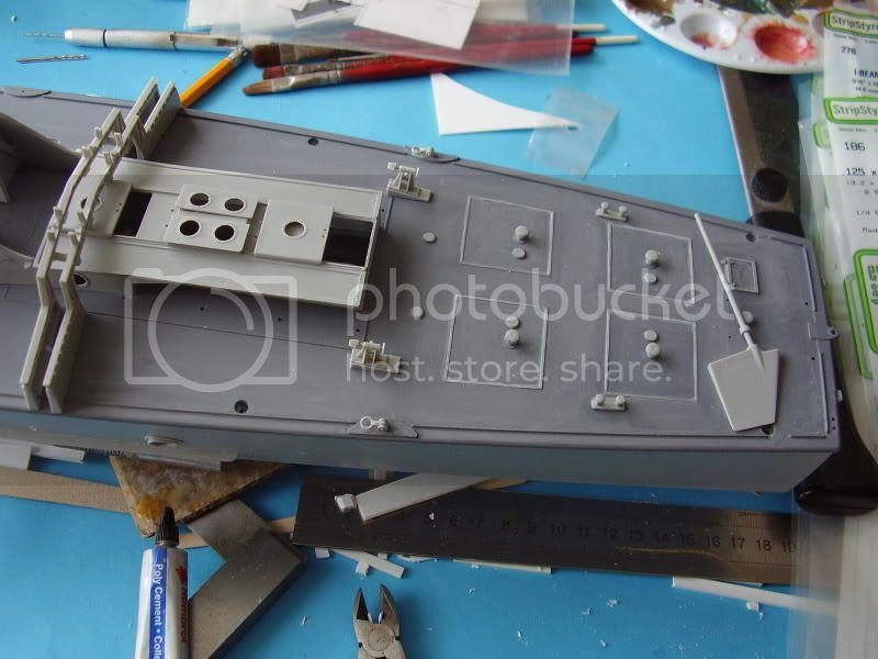
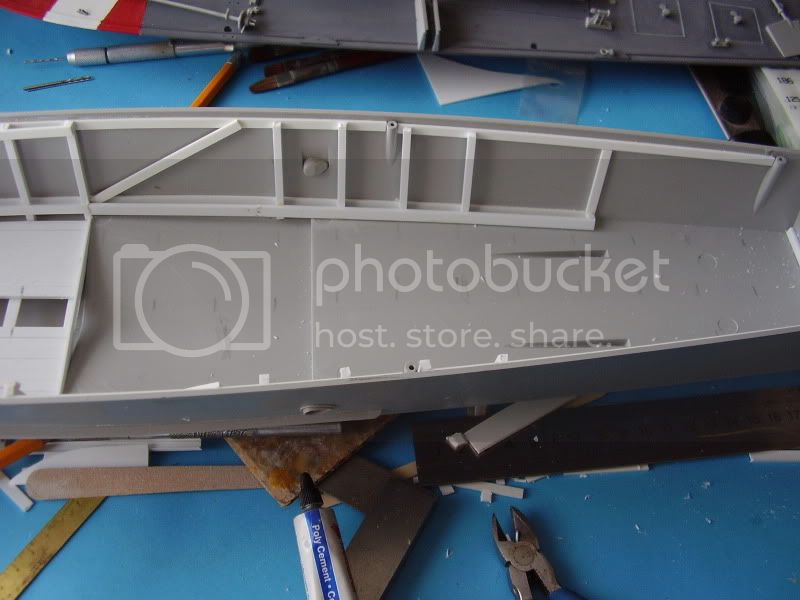
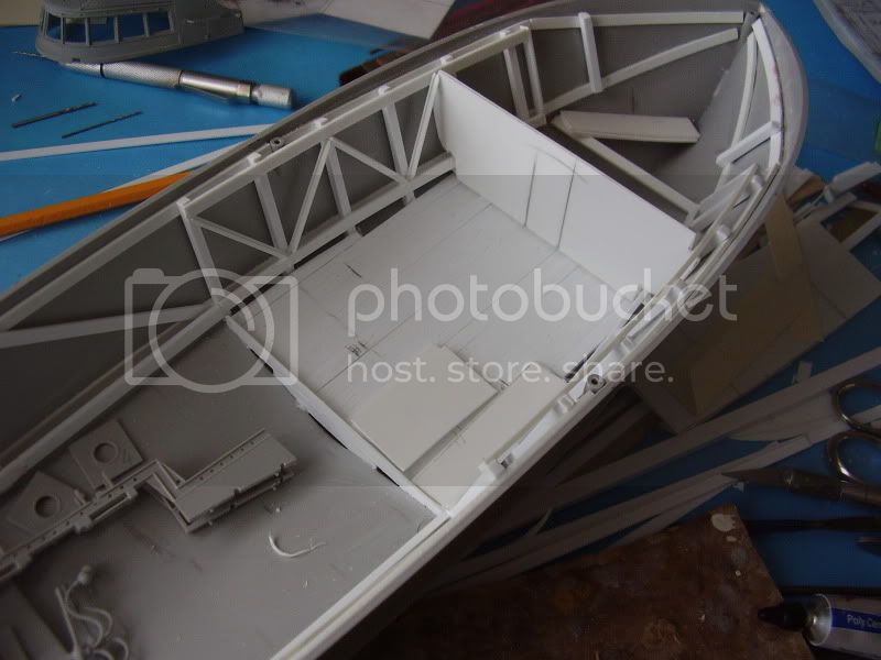
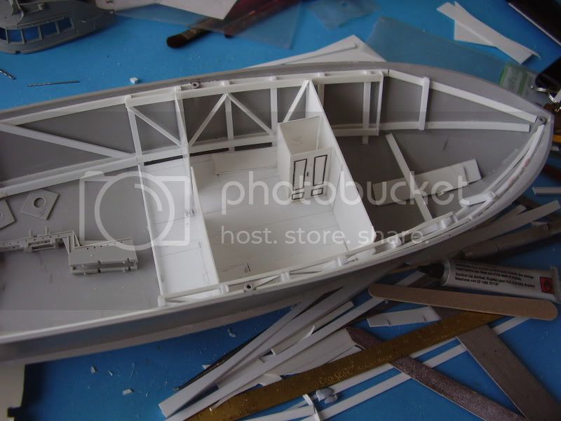
 Here are the inboards for the forward section:
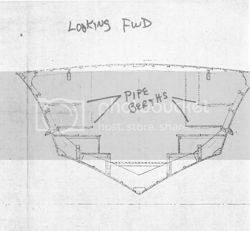
 .
. 


Hi folks,
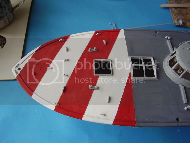
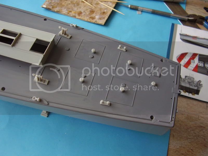
A couple of questions. Would anyone know if the planking on the cabin decks ran port to starboard or bow to stern? Also what height would the cabins have been (floor to upper deck)?
Thanks
Al


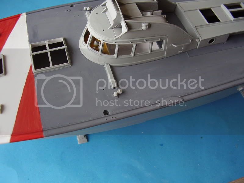
Quoted TextWould the internals of the cabine be in white?
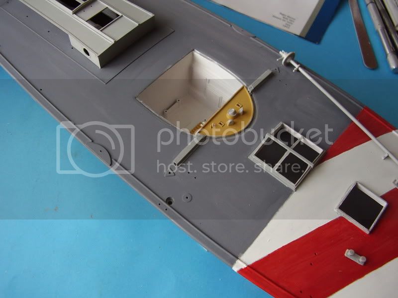
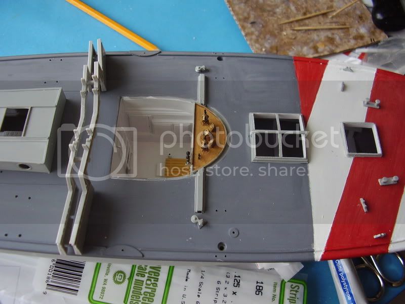
Does anyone have a picture of any other parts of the internals, In thinking of what lies under the forward skylights/hatch.
Al
White is a common interior color for small craft.
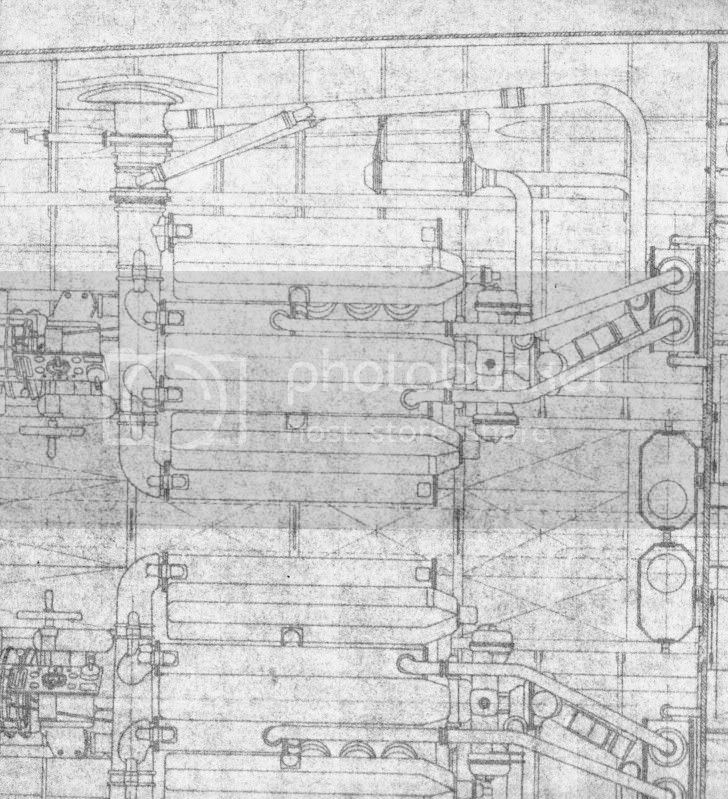
These are two sections looking forward, in the 4th series boats, from the original Baglietto plans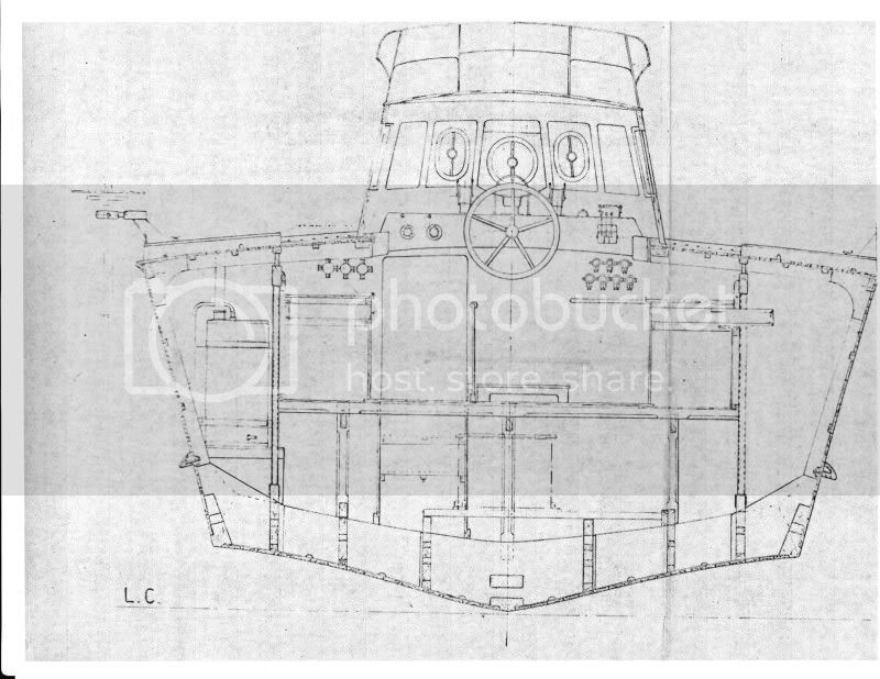
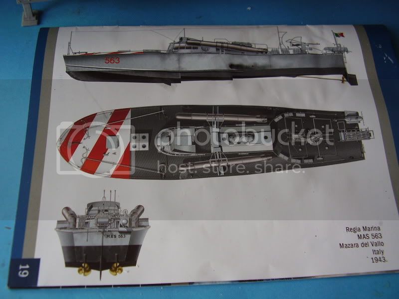
This is a color rendering from the Italian naval camo book by Bagnasco and Brescia:
The colors are representative. I don't use Tamiya colors, so can't provide any similarities. In the book, the colors are somewhat like FLOQUIL Reefer Gray and SP Lettering Gray.
Al Ross
the top diagram. Is what looks like a door, the side of the locker? If so then am I right in thnking there was no connecting door between the crew and officers cabins??


Were the fuel tanks either side of the Helm and what if anything was stored in the stern at the back of the engine room?


 Was the radio walled off as in the diagrams? Or have I mis-read that?
 |