_GOTOBOTTOM
General Ship Modeling
Discuss modeling techniques, experiences, and ship modeling in general.
Dreadnoughts!! Tread's 'Elephant Man' entry..
TreadHead
Visit this Community
Colorado, United States
Joined: January 12, 2002
KitMaker: 5,000 posts
Model Shipwrights: 453 posts
Posted: Sunday, October 16, 2005 - 06:54 AM UTC
Howdy All,

As promised, here is the beginning of my thread regarding what I have dubbed, my 'Elephant Man' entry for the Dreadnought Campaign. I have chosen this moniker for my build because my choice of subject matter is rather unattractive and/or hideous compared to the beautiful lines and the sheer grandeur of true 'ships of the line', such as the USS New Jersey, or the Bismark....
My entry fits the discription also because it has, for the most part, been keep hidden behind an analogous cloak of darkness, and kept from view of the more timid-hearted....for their own protection of course...

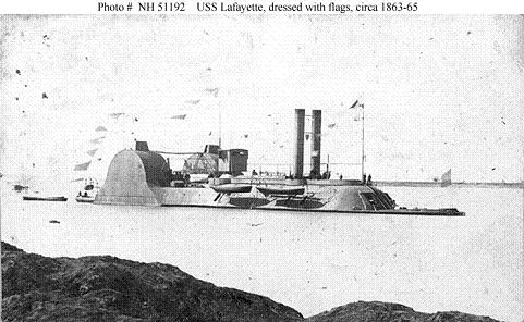
My entry {as if some of you didn't already know} , is the American Civil War Ironclad, the U.S.S. Choctaw. For those who may be interested, here is some background on this rather unique ship.....

U.S.S. Choctaw

Class: Casemate Ram
Overall Dimensions: Length 260', Beam 69', Draft 8'
Total Displacement: 1,004 Tons
Top Speed: 7 Knots
Crew: 106
Armor thickness: 2" casemate, 1" rear casemate, 1" sides, 2" pilothouse
{this was done in an 'offset' arrangement, lower layer horizontal/upper layer vertical, or visa versa}
Armament: Three 11" Dahlgren smoothbores, two 30 pounder Parrot rifles, two 24 pound Standards


Originally built in 1856 at New Albany, Indiana as a side-wheel merchant steamer. Acquired by the Government in September 1862, her conversion to a warship was begun using plans by Commodore William D. Porter but these were altered while work was underway. Commissioned in March 1863, Choctaw was a singular-looking vessel, probably the most imposing in appearance of any of her Mississippi Squadron contemporaries.

The U.S.S. Choctaw's operational career began with a bombardment of Haynes' Bluff, on the Yazoo River, Mississippi, in late April and early May 1863. She was hit 53 times in this action, with many shots penetrating her armor, but casualties among her crew were light. Later in May, she participated in the capture of Yazoo City and the destruction of the Confederate Navy Yard there. In March-May 1864, the U.S.S. Choctaw was part of the large Naval force that took part in a major campaign on the Red River, in Louisiana. She was decommissioned in July 1865, after the end of the Civil War, and was sold in March 1866.

Without further ado, I will try to post pictures of my build progress....due to not being able to find the CD I burned some of my images on, I will post the pics I do have in a somewhat non linear fashion....my apologies for the inconvenience

The Beginning:

I am building the main 'armature' of this project out of what's called MDF. A dense composite sheet of wood product used by Hollywood for many a movie prop. It comes in 4' x 8' sheets, and can be easily purchased at your local lumber store.
The picture below is a cutout of the Main Hull outline. Since there are no plans or naval architectural drawings that exist for this ship, the outline was acquired by some very deep research, and by the kind and generous assistance by fellow ACW naval aficionados....
This outline was then traced out on a piece of 3/4" particleboard {I made the mistake of using this material first.....believe me, MDF is much easier to work with!} and cutout using a combination of a circular saw and a common jigsaw {if you look closely you can make out the dimensional lines that assisted in ensuring the accurate cutout, and the interrelationship between upper and lower components}. These seperate cuts {the straight cuts and the curves} were then sanded and blended together with a hand belt sander.. This gave me the basic shape of the main hull ouline.....


Now, with this cut out, I then cut strips of Evergreen sheet stock the same height as the hull waterline and etched panel lines every 2 (scale) feet in a vertical orientation to simulate the individual sheets of iron 'cladding' and CA glued them to the sides of the hull. Following this up with cutting out the wood decking from {again} Evergreen grooved sheet stock , and gluing down in place......
Here is the Main Hull piece with full perimeter waterline cladding and bow and stern decking installed...
{the 'bare' area in the center is where the Main casemate/crews quarters sits}

And here is a close-up of the bow section to give you an idea of the 'cladding' going on.....


On to the Main Casemate;
This was quite a bit harder than the rather simplistic Main Deck construction. Mainly because it not only required a total of three (3) laminated sheets of MDF, but, it also required those laminated sheets to be sanded and shaped into a series of complex curves. Not only reversing themselves, but being convex in one section of the casemate, while slowly transversing to concave at the other end....
This photo shows the casemate complete with a significant amount of 'cladding' added.....

The rounded, oblong area at the front of the casemate has a flat area atop it which will have decking installed, and a set of railing added. The lower, flat stretch of casemate between the oblong area and the rear rise, will have 'boardwalk' style planking installed above the standard decking which served as a 'fast' route between the elevated observation platform and the rear-mounted operations area. The rear section of the casemate {at the rear of the picture} will accomodate the crew area housing and have both of the rather prominent paddlewheel structures mounted on top and to either side of the housing units....

Now, I'm not sure if you can see the convex/concave curves in the photograph {sorry about the poor photographic skills}, but in order to create the overall shape of this casemate, including all of the compound curves, I was forced to use a rather delicate, fine woodworking tool {you carpenters out there will get a 'kick' out of this! }
All sanding, shaping, curve making, and blending, was done with this wee thing...........no kidding.....


Now that I've probably bored you all to tears with this rather lengthy post, I will take a breather to at least make sure my posted pics are showing up................

warm regards,

Tread.
blaster76
Visit this Community
Texas, United States
Joined: September 15, 2002
KitMaker: 8,985 posts
Model Shipwrights: 3,509 posts
Posted: Sunday, October 16, 2005 - 07:22 AM UTC
Gordon:

How big is that thing !!!!!!!!!!!!? It looks 3 to 4 feet long. When did you take the pics, it looks like summertime out there and I know Colorado has recently been clobbered by snow while we here in Dallas are enjoying our "fall" weather of 85 degrees. (last week it was in mid 90's) :-)

Sorry man just had to rub it in a bit. I lived in Colorado Springs / Ft Carson in mid 60's

Build is most impressive. Where are you planning to get fixtures and stuff for the detailing? Aer you going to scratch those out too?
TreadHead
Visit this Community
Colorado, United States
Joined: January 12, 2002
KitMaker: 5,000 posts
Model Shipwrights: 453 posts
Posted: Sunday, October 16, 2005 - 09:45 AM UTC
Howdy Steve,

Many thx for stopping by and viewing my 'Elephant Man'

To answer your queries;

Yes, it is indeed about 3 feet long. Mighty large I know, but it is being built with a 'home' already in mind.
As far as the pics {and the "rubbing in" }, the first three photos were taken at an earlier date {obviously not including the shot of the Choctaw itself}, the last two were taken this morning.....sorry to tell ya pard', but it's been almost 80 here today too..

Now, as far as "fixtures and stuff". One of the main reasons I chose to build this project in 1/87th scale instead of the usual museum scale of 1/96th scale is; that many supporting pieces can be had in either HO scale, or even ROCO scale......believe me, helps big time. Especially when proper "museum" scale is random at best......

More to come for when the rest of the Warship 'crew' checks in from their respective "Vaa Caa's".......

thx again for stopping by.......

Tread
skipper
Visit this Community
Lisboa, Portugal
Joined: February 28, 2002
KitMaker: 5,182 posts
Model Shipwrights: 4,070 posts
Posted: Sunday, October 16, 2005 - 10:19 AM UTC
Hi Gordon

I am loving your "Elefant Man" - as stated before in other posts! I am glad this Campaign has pushed you to work on the Choctaw!

Keep up the good work,

Skipper
Gunny
Visit this Community
Pennsylvania, United States
Joined: July 13, 2004
KitMaker: 6,705 posts
Model Shipwrights: 4,704 posts
Posted: Sunday, October 16, 2005 - 10:29 AM UTC
Ahoy, Gordon!
Things are about to get a little more interesting with this campaign, thanx to your sudden appearance at the muster station, Mate!...That is going to be a MONSTER, Dude!...do keep us posted with lots of pics and progress banter, Tread...looks great!
Gunny
TreadHead
Visit this Community
Colorado, United States
Joined: January 12, 2002
KitMaker: 5,000 posts
Model Shipwrights: 453 posts
Posted: Sunday, October 16, 2005 - 11:04 AM UTC
Howdy Rui...Gunny,

Again, just for the record, I am in your debt for voting favourably on my Choctaw inclusion in this superb Campaign.
I count myself fortunate to be in the same company as the rest of the stellar cast you have assembled here with this 'Big Ship' build. Some of the in-progress photos are nothing less than inspiring to say the least! Bully for both of you for giving this Campaign some supercharged legs....

For those interested, I am a wee bit further along than the photos would indicate, but I am trying to assemble a decent, linear pattern to my photo posting madness.....originally I intended a "PhotoBuild Article"....but unfortunately time is not my friend as of late, so this method works just dandy since I cannot figure out how to put all that together...

So, here's a few more of the Elephant Man....

This first shot {below}, is of the general, overall shape of the ship itself.....

As you can see, the ship is quite long, and uniquely shaped. The front of the vessel displays the bulbous shape of the main casemate along with the elevated front section, overshadowed ever so slightly by the more heavier stern section with it's somewhat predominant armoured paddlewheel housings......

I began the process of applying the simulated iron 'cladding' by this process;

First, I would sketch out the outline of the individual sections of armour along the walls of the casemate {for example} in somewhat heavy lead pencil so that I could see it easily....then, I took a small piece of regular tracing paper and overlaid it over the section to be copied and traced out the lines beneath onto the tracing paper.....


Once this is done, I would then glue {using simple Elmer's glue} the tracing paper to a sheet of .020 sheet styrene.....


Once applied and given just a few seconds to adhere, I would then cut along the lines in the tracing paper thereby tranferring the shape to the sheet styrene.....


Once done you would have the proper shape cut almost to the exact shape you desire.....


At this point, just peel off the tracing paper, and glue the accurate sections of 'cladding' to the model....
remembering to 'etch', {using the back side of my Xacto knife}, the dividing lines betwix the iron plates. In this fashion you have the ability to slightly bend the cut piece of styrene and create a natural 'bend' in the plating so that the piece will bend around your curved casemate surfaces......


Voila!.......with any luck, you've got yourself the beginnings of an Ironclad!

Tread.
Gunny
Visit this Community
Pennsylvania, United States
Joined: July 13, 2004
KitMaker: 6,705 posts
Model Shipwrights: 4,704 posts
Posted: Sunday, October 16, 2005 - 11:17 PM UTC

Quoted Text

Howdy Rui...Gunny,

Again, just for the record, I am in your debt for voting favourably on my Choctaw inclusion in this superb Campaign.
I count myself fortunate to be in the same company as the rest of the stellar cast you have assembled here with this 'Big Ship' build. Some of the in-progress photos are nothing less than inspiring to say the least! Bully for both of you for giving this Campaign some supercharged legs....

Tread.


Right back at ya, Gordon!...I consider it an honor to have a talent such as yours involved in this campaign build (you're making this entry of yours look very easy! ), and I sincerely am looking forward to seeing your advancing progress with this most interesting of subjects...Bravo, Tread, keep it up, mate!
Gunny
redneck
Visit this Community
Pennsylvania, United States
Joined: June 06, 2005
KitMaker: 1,602 posts
Model Shipwrights: 665 posts
Posted: Monday, October 17, 2005 - 02:31 AM UTC
Wow Tread that’s a great job so far.

I really look forward to seeing the completion and progress of this ship.
I love both the design of this ship and the amount of wood going into it.

I do wood work myself and can just imagine how difficult that casemate must have been. You did a very good job with it.

Keep up the good wook.
TreadHead
Visit this Community
Colorado, United States
Joined: January 12, 2002
KitMaker: 5,000 posts
Model Shipwrights: 453 posts
Posted: Monday, October 17, 2005 - 05:16 AM UTC
".......Right back at ya, Gordon!...I consider it an honor to have a talent such as yours involved in this campaign build (you're making this entry of yours look very easy! ......"

Howdy Gunny,

Thank you Sir, I am indeed humbled by your kind remark As to making it look "easy".....well, I have always believed in a simple motto, and that is; "Just 'A,B,C" me once would ya?"
Meaning, that I feel if you take the time to break something down to the basic technique, and literally show me something as if I was in Kindergarten, I will retain it, and remember it......being an Architect I used to regularly discuss very involved details of construction, and found through experience that, verbal interpretation can be a writhing monster of misunderstandment.......so, I got into the habit of saying to the Engineer or to whomever I was speaking to, "Just 'A,B, C me, would ya?".........worked every time. Thing is, almost no one ever did that for me...so, in order not to be a hypocrite, I felt that if there is anything I can pass on, no matter how simplistic it may seem, somebody else out there will have learned something....as I try to do everyday. The method I used for tranferring complex shapes to styrene {using the glued down tracing paper} seems overly simple to most of us maybe....but to some, it might be one of those smack yourself in the forehead and say "Duh!" moments.....

to redneck: Again, thx for the kind words of encouragement Since you've done your share of wood work, I think you can get an idea of how masochistic I must have been to decide to use a 3" wide commercial belt sander to do all of that shaping!... But, I have only myself to blame. A Dremel would have been MUCH easier, and a whole lot less strain on the ol' patience meter.....
But, for what it's worth, I've gotten pretty darn good at manipulating that behemoth.....so much so that I'm continuing to use it on one of my other large-scale Ironclad projects, the U.S.S. Osage. Only, on the Osage, the vast majority of the 'shaping' is being done on the horizontal surface of the deck, and not along the vertical surfaces of the casemate.... plus, there's only one basic curve, and that's convex, mucho easier than concave!

For the record, I've got some more photos of how I did the cannon apetures in the casemate using my nifty new air-powered mini die grinder......will post them in a wee bit.

regards,

Tread.
Halfyank
Visit this Community
Colorado, United States
Joined: February 01, 2003
KitMaker: 5,221 posts
Model Shipwrights: 1,821 posts
Posted: Monday, October 17, 2005 - 05:38 AM UTC
I've been AWOL here for a while, at least on the Warships forum, but I've been lurking. That's a VERY interesting subject Tread. It's certainly a bit weird looking, but I'd hardly call her ugly. They say form follows function and her function made her form what it was. Really looking forward to seeing more of her.

TreadHead
Visit this Community
Colorado, United States
Joined: January 12, 2002
KitMaker: 5,000 posts
Model Shipwrights: 453 posts
Posted: Monday, October 17, 2005 - 09:22 AM UTC
Howdy Rodg',

Mighty nice of you to drop by pard' I too have been UA from the site for a while....and I also try to lurk whenever I get the chance....pretty much to keep an eye on the likes of you so that none of the heathen's get out of hand.............

Regarding your statement ".....They say form follows function and her function made her form what it was. ....."
In most cases you would be right, but in this particular case, I think it was more a matter of 'using what ya got'
Truth be told, the overall design of both the U.S.S. Choctaw and the U.S.S. Lafayette, was flawed from the beginning. Disregarding the facts that her {steam} engines were severely underpowered, and that her draft was a tad deeper than desired, her overall length made her extremely hard to maneuver between the banks of the rivers she operated along....fact is, she could literally turn 180 degrees {or 360} on her own length if desired {and did it a couple of times}, but it took her all afternoon to do so!
She did have an active battle history, and served the Union Navy well during her active duty life span. My interest in her is based upon here rather unique lines, and the fact she is a paddlewheeler and not a screw powered ship........always had a ' thing' for paddlewheelers.............

Tread.
Halfyank
Visit this Community
Colorado, United States
Joined: February 01, 2003
KitMaker: 5,221 posts
Model Shipwrights: 1,821 posts
Posted: Monday, October 17, 2005 - 11:13 AM UTC

Quoted Text

........always had a ' thing' for paddlewheelers


You might be interested in a book I picked up a while back, Hard Luck Ironclad. It's about the career and salvage of the USS Cairo, a side wheeler iron clad that struck a Confederate mine.

It's yours if we ever meet. I was up your way a couple weekends ago at the IPMS Region 10 show. I think I remember you're not keen on IPMS so I didn't try to contact you.

blaster76
Visit this Community
Texas, United States
Joined: September 15, 2002
KitMaker: 8,985 posts
Model Shipwrights: 3,509 posts
Posted: Monday, October 17, 2005 - 04:52 PM UTC
Are you going to have any of the apperatures open and cannon (barrels) displayed? As to ironclads, I have always loved those Confedeate Rams like the Tennessee and the Arkansas
TreadHead
Visit this Community
Colorado, United States
Joined: January 12, 2002
KitMaker: 5,000 posts
Model Shipwrights: 453 posts
Posted: Wednesday, October 19, 2005 - 04:39 PM UTC
Howdy fellas,

To Rodg':
Many thx pard' for the kind offer of the book...not only do I enjoy anything about Ironclads, but, I can never get enough books! Add to that the big plus of maybe finally getting to meet you, and it's an offer I just can't refuse......now, all I need is the time....something I'm sure neither of us have enough of......

The Ironclad of which you speak is an interesting story, and the salvage efforts are admirable, I wish the Cerberus was getting as much attention.....but I digress
For those out there who are not familiar with the vessels we are talking about, below is a photo of the Cairo.....


From the photo I believe it was actually a sternwheel configuration {you can see the rounded, armoured paddlewheel enclosure at the stern of the vessel}, with the small pilothouse just in front of the smoke stacks...
From the photo you can see one of the gun apeture arrangements that the Union Navy employed. The Union Navy had two popular methods in which they opened the gun apetures prior to rolling the cannons into firing position.
One was where the door slide up a channel, and the other was where the door simply raised up on a hinge {pictured}.
As a comparison, the Confederate Navy for some reason opened their gun ports by pivoting their doors to the left, or to the right of the apeture......{probably more information then any of you want huh?.....sorry, couldn't help myself... }

to Blaster:
To answer your question, I will post this update.

Elephant Man continued......

Because the cannons onboard a Civil War Ironclad are so much a part of what they are, I decided to show them in the 'open' position on my U.S.S. Choctaw. Now, since the casemate I have built is a solid piece of MDFand not a hollow shell, I needed to come up with a way to router out each of the apeture openings. Not only route them out, but do it in a way that the portion removed would line up with the straight-edged sides, top and bottom of the opening itself....

Here's what I came up with;


The 'router' tool you see in the photograph is a nifty little item I picked up at one of my {becoming} favourite tool stores, Harbor Frieght. It is a mini die grinder, that is air powered. and only cost me $14.99....excellent price
The mini, diamond circular cutting wheel you see attached was also purchased there. What I did was use the straight cutting edge of the cutting wheel and very carefully cut right along the edge of my gun port opening on both sides right up to the top and bottom edge....I repeated this for all the openings...

Next, I changed out the cutting wheel on my mini die grinder for a tapered diamond rasp baton and {again} very carefully ground away at the MDF material until I came to the flat walls of my previous cuts...


I did this until my routered 'holes' were deep enough that the interior looked hollow from the outside looking in and there was enough room to insert the Dahlgren cannons, and Parrot Rifles at a later date.....

I haven't decided yet if I'm going to try to search for a pre-made set of cannon tubes to stick in the opeings, or, drive myself crazy employing a lathe and making them myself.............any suggestions?

Tread.

UP NEXT.......the operations area/crews quarters at the stern of the ship {hopefully.....}
Gunny
Visit this Community
Pennsylvania, United States
Joined: July 13, 2004
KitMaker: 6,705 posts
Model Shipwrights: 4,704 posts
Posted: Wednesday, October 19, 2005 - 11:38 PM UTC

Quoted Text

I haven't decided yet if I'm going to try to search for a pre-made set of cannon tubes to stick in the opeings, or, drive myself crazy employing a lathe and making them myself.............any suggestions?


Greetings, Gordon!
I want to tell you that I really am enjoying this build that you are sharing with us, and now included in the Dreadnoughts! Campaign...I think that these old watertanks are completely amazing creations, and your re-creation is coming along beautifully...quite ironic, but just yesterday morning there was a really cool special on "Voyages" at the History Channel about the Ironclads, and although there was no mention of this particular subject I swear that there was a photo shot or two showing this example...keep up the great work and postings, Tread!...and about the cannon tubes, I think you should break out the lathe and turn them yourself...keep it 100% homemade!
Gunny
redneck
Visit this Community
Pennsylvania, United States
Joined: June 06, 2005
KitMaker: 1,602 posts
Model Shipwrights: 665 posts
Posted: Thursday, October 20, 2005 - 12:36 AM UTC
She’s coming along nicely.


I have to agree with Gunny about doing it yourself.
I always like to do things myself one possible.

If you do make them yourself are you planing on using metal or wood?

I don’t know what equipment you have available but if your making it out of wood the cannons may be to thin for most lathes. It might be easier mounting it in a drill press and sanding it down.
Just an idea.


I’m looking forward to seeing mor on this ship.
TreadHead
Visit this Community
Colorado, United States
Joined: January 12, 2002
KitMaker: 5,000 posts
Model Shipwrights: 453 posts
Posted: Thursday, October 20, 2005 - 02:17 AM UTC
Howdy fellas , and "Good Mornin' to ya!

Many thx for stoping by again and doing your part to keep the Warship side of this site alive! Even though there are obviously fewer souls here who embrace the 'salty' side of modeling, I think that those of us here who in fact do dabble in this form of modeling need to take every opportunity presented here on the Forum's to raise 'Warships' up on our shoulders and raise our voices so that they might be heard by others.....remember, at a place called Armorama, we ship modelers have to act like the car rental company Avis, and "...try harder".....

Anyway, {slipping the soapbox back underneath the couch...} thx for your comments. Especially the ones about "doing it myself"...Ahhhhhhhhh!!!!!....I was hoping everyone might embrace 'storebought' cannon tubes, to at least preserve my sanity...but then, taking on a project of this size already proves I'm insane! So, I'll begin seriously considering lathing my own........

to Gunny:
Thx for the heads up on the "Voyages" TV program, for some reason that sounds familiar, I'll have to keep my eyes open for it next time.....especially since there is SO little available out there regarding Ironclads.

to redneck:
To answer your question directly; I guess I'm going to {if I decide to} have to make them out of wood. Since I don't own a proper metal lathe, I really have no choice....but that brings me to another nifty little item I picked up at Harbor Freight...a mini dual grinding wheel, complete with a handheld takeoff on one end for a moto-tool {sorry, don't have a photo as yet} for the record, I've made 'adjustments' at the end that has the takeoff, and mounted a mini drill chuck in place of the moto tool.....Voila!.....I have a simple, effective lathe for under $30 sheckles!!......

........more later, gotta run,

Tread.

Gunny
Visit this Community
Pennsylvania, United States
Joined: July 13, 2004
KitMaker: 6,705 posts
Model Shipwrights: 4,704 posts
Posted: Monday, November 28, 2005 - 02:14 AM UTC
Hey Gordon!

Where are ye, mate?...haven't heard anything about your elephant man entry as of late...fill us in on an update!

Gunny
 _GOTOTOP