_GOTOBOTTOM
Ships by Class/Type: Military Support Vessels
Non-combat support vessels of any type and post-sail.
Hosted by Harry
Chitose! Building Aoshima's Seaplane Tender
JPTRR
Staff MemberManaging Editor
RAILROAD MODELING
#051
Visit this Community
Tennessee, United States
Joined: December 21, 2002
KitMaker: 7,772 posts
Model Shipwrights: 476 posts
Posted: Friday, November 15, 2013 - 01:51 PM UTC
Recently I received the 1/700 Nihon Kaigun (Imperial Japanese Navy) Chitose, a Nisshin-class seaplane tender. (You can read the review here: Review of IJN Chitose .)

The model appears to be mainly new sprues, and there are a lot of them. I have started the model per the instruction sequence, adding or holding off a few small items per my assembly techniques. Not much to show so far, but a start!

The bridge: so far about 15 pieces to this sub-assembly, with more on the way (including 1/700 life rings)! Fit is OK although not as gapless as I'd like; of course the gaps are pretty thin.


The hanger deck. Nicely detailed top and underside. Aoshima has a release with P/E but this isn't it.


The hull. Curiously, the base and the one-piece hull set flat on the table prior to joining them. They click together with pins in the base fitting into internal pads in the hull. The fit was tight and afterwards the hull has a slight bow.

What are these you ask? I'm not certain and haven't looked ahead in the instruction sheet to figure them out!

Check back soon!
TimReynaga
Staff MemberAssociate Editor
MODEL SHIPWRIGHTS
Visit this Community
California, United States
Joined: May 03, 2006
KitMaker: 2,500 posts
Model Shipwrights: 1,830 posts
Posted: Friday, November 15, 2013 - 05:45 PM UTC
Frederick,
I built sister Chiyoda long ago (Aoshima's 1970s version - and I didn't do it justice!) If you haven't already done so, I recommend picking up the Gold Medal Models IJN Auxiliary set http://www.goldmm.com/ships/gms7027.htm to upgrade the cranes.
This is a nice kit, best of luck with it!
Quincy
Visit this Community
Oklahoma, United States
Joined: October 29, 2008
KitMaker: 99 posts
Model Shipwrights: 97 posts
Posted: Wednesday, November 20, 2013 - 05:23 AM UTC
They look like generators or possibly winches??


Bob Pink.
warreni
Visit this Community
South Australia, Australia
Joined: August 14, 2007
KitMaker: 5,926 posts
Model Shipwrights: 2,624 posts
Posted: Wednesday, November 20, 2013 - 07:14 AM UTC
After much deep thought and consideration I think they are blobs of styrene!

All jokes aside even though I don't 'do' 1/700 I am following with interest. Well done so far Mr Boucher..

Cheers
Warren
Shanghaied
Visit this Community
Schleswig-Holstein, Germany
Joined: June 30, 2011
KitMaker: 189 posts
Model Shipwrights: 106 posts
Posted: Thursday, November 21, 2013 - 03:04 AM UTC
Could the blobs have something to do with a landing sail?
That was a device quite common before WW2 to smooth the water surface for the landing planes and make it more easy to pick up with the crane.
German ships had these landing sail but gave up because you have nearly the same effect by letting the ship make a duckpond.

Just an idea

Greetings from Shanghai
JPTRR
Staff MemberManaging Editor
RAILROAD MODELING
#051
Visit this Community
Tennessee, United States
Joined: December 21, 2002
KitMaker: 7,772 posts
Model Shipwrights: 476 posts
Posted: Friday, November 29, 2013 - 05:17 AM UTC
Thanks for the input, gents.

Now that turkey day is past I plan to have soem more progress shots forthcoming soon!
JPTRR
Staff MemberManaging Editor
RAILROAD MODELING
#051
Visit this Community
Tennessee, United States
Joined: December 21, 2002
KitMaker: 7,772 posts
Model Shipwrights: 476 posts
Posted: Friday, January 03, 2014 - 02:41 PM UTC
I have been MIA over the holidays and am happy to update that in the next week I should be posting more pix. I have the linoleum decks primed and waiting for warmer weather to shoot the paint. Some further fiddly assembly has taken place, too.

BTW, I hate to ask but was the elevated aircraft deck linoleum, too? The instructions show it as steel yet the molding indicates it should be linoleum.

Very sorry for the delays.
TimReynaga
Staff MemberAssociate Editor
MODEL SHIPWRIGHTS
Visit this Community
California, United States
Joined: May 03, 2006
KitMaker: 2,500 posts
Model Shipwrights: 1,830 posts
Posted: Friday, January 03, 2014 - 03:48 PM UTC
Fredrick,

I couldn't find any definitive information on the elevated aircraft deck, but this picture of sister Chiyoda seems to show the deck as the same tone as the surrounding linoleum covered decks...so maybe linoleum?

JPTRR
Staff MemberManaging Editor
RAILROAD MODELING
#051
Visit this Community
Tennessee, United States
Joined: December 21, 2002
KitMaker: 7,772 posts
Model Shipwrights: 476 posts
Posted: Wednesday, January 15, 2014 - 06:45 PM UTC
Ahoy!

Best-laid plans of mice and modelers... But now I'm back and here is progress!

I don’t know the release date of the original Aoshima Chitose. One sprue with aircraft and auxiliary pieces has ‘1994’ molded on it.

Fit of the parts is generally good. Some of the smaller assemblies, such as the hanger superstructure towers, are slightly out of line despite alignment pins and holes.


If the model was a larger scale this would be almost imperceptible. However, with this model a fraction of a millimeter will misalign some parts enough to notice.

Setting the weather deck into the hull was very easy and looks great. Aoshima cleverly engineered the model with beveled edges inside the gunwale and along the interior edges of the five deck pieces. This allows a very tight and flush fit creating a sharp demarcation between the top edge of the hull and the linoleum deck parts.


Pay attention to the sequence of decking. The bow deck anchor handling gear overlays the forward weather deck and must be inserted after seating the forward weather deck.


Aircraft ramps on the hanger deck overlay the rear edge of that forward weather deck. The aft weather deck and the stern deck require no particular order. Alignments of the decks are ensured by small alignment pegs and slots under the weather decks, and by the contour of the hull.


I used the weather decks to space the other decks and then removed them. The decks of my model fit so well that I did not immediately need glue. I then removed the weather decks and used an extra thin glue and capillary action to bond the hanger and stern decks to the hull.

Once the decks are down there is not any convenient gap to apply the glue, risking excess glue damage. If I had it to do over, I would drill access holes for the glue applicator through the underside of the hull and apply the glue from within.

I decided to paint the linoleum weather decks prior to gluing them. With the linoleum sheathed weather decks removed, I painted the model. To keep nasty paint out of the beveled area the decks set into, I squirted white glue inside the gunwales.


It peeled off without trouble after the paint dried.


I used Tamiya XF-75 IJN Gray (Kure Arsenal) thinned with Lifecolor Thinner. While the paint was still wet I added a few drops of Vallejo Chalk White, more thinner, and misted it over the topsides of the ship. Then I dipped a stiff bristle brush into the airbrush reservoir and used my flick-painting method across all surfaces. (You can easily see the dried spatter inside the hull and on the ballast metal bar.)


This created a subtle splotchy finish.

Next, sub-assemblies!
JPTRR
Staff MemberManaging Editor
RAILROAD MODELING
#051
Visit this Community
Tennessee, United States
Joined: December 21, 2002
KitMaker: 7,772 posts
Model Shipwrights: 476 posts
Posted: Thursday, January 16, 2014 - 06:00 AM UTC
Hanger Deck

I don’t know if "hanger deck" is the proper term for the area midship with the elevated deck, yet that is how I will refer to it. The weather deck here is non-skid plate uncovered by linoleum (like the bow and stern decks). The deck part has an elongated oval in the middle and held ridged by a sprue within, which I cut out. That opening was covered multiple large hatches which retracted on tracks towards the gunwales. Those are modeled by two long parts representing the multiple hatches.


If one wanted to go through the trouble the cavity could be boxed in and the hatches positioned open. Those hatches hardly have anything to keep them from falling through the opening and if I had it to do over again, I would have left the sprue in the void. The starboard cover has tiny corners that overlap the deck and I surmise that is how Aoshima intended the part to be supported. Then the port part butts against it. Gentle handling is required while setting and gluing these pieces.

Slots in that deck align the towers that elevate the upper hanger deck. The four towers are multipart assemblies, some with very fine parts such as pipes and vents. These towers also held cranes. Each tower has a front and back piece, with alignment holes and pegs. I found the parts not to join neatly, leaving gaps and steps where they seat to the decks. Three have molded mounting holes for equipment but one requires a .6mm drill to open several holes (a notice I didn’t notice until the parts were joined).

The elevated deck is a visually interesting assembly of weather decking, an underside of girder work, with separate girderwork sides.

Several searchlights, AAA guns and other equipment will be added. The weather deck is molded with transvers raised lines that represent the brass bands anchoring the linoleum anti-slip used by IJN. Most modelers consider this surface to be steel plate. I decided to paint it as linoleum. (Thanks for the photo, Tim!)

The crane towers that hold that deck up have tabs that fit into slots in the bottom of the elevated deck and into the hanger deck. It is pretty wobbly getting them lined up plumb. I glued two towers, let them dry, then the others. Since the tower halves did not mate straight and had slight steps where they mate to the decks, I weighted the assembly as the glue cured.


The towers are glued into the elevated deck. I am debating whether to cut the tabs from the bottom and force the feet to set flush on the hanger deck. Check back!
russamotto
Visit this Community
Utah, United States
Joined: December 14, 2007
KitMaker: 3,389 posts
Model Shipwrights: 151 posts
Posted: Thursday, January 16, 2014 - 06:33 AM UTC
Looks really nice. White glue has many uses.
JPTRR
Staff MemberManaging Editor
RAILROAD MODELING
#051
Visit this Community
Tennessee, United States
Joined: December 21, 2002
KitMaker: 7,772 posts
Model Shipwrights: 476 posts
Posted: Thursday, January 16, 2014 - 07:10 AM UTC
Sub Assemblies

Here is the forecastle and bridge, 12.7 cm/40 Type 89 main battery, and stack.


Note that to properly position the stack and the correct angle, Aoshima molded a "D"-shaped tab and slot.

They did the same for the stack exhaust screen. Despite the screen's alignment tab/slot, it went on askew!

Now, how to hand-paint those brass bands... I already have an idea, courtesy an art store!
JPTRR
Staff MemberManaging Editor
RAILROAD MODELING
#051
Visit this Community
Tennessee, United States
Joined: December 21, 2002
KitMaker: 7,772 posts
Model Shipwrights: 476 posts
Posted: Tuesday, January 21, 2014 - 05:54 PM UTC
Progress. Not sure if I'm happy with it.

The brass bands on the deck: several tries failed me until I bought a Prismacolor artist pencil. It is what I used to "brass' the bands. Although they are slightly raised, keeping the colored core on them is difficult. I eventually gave up freehanding and used a straightedge.

I found that while the pigmented lead will stick to the raised bands, the bands are so narrow that the color is almost imperceptible. I began drawing on the deck next to each band, using the band for a guide. Scrutinize the four photos and let me know what you think?


After drawing the bands I touched up the linoleum. I haven't found any account concerning the durability of that non-slip. I presume that it, too, weathered and required spot-replacement. Hence, I am not terribly worried that the touch-up causes slight variations in the decking.

Next, I painted all of the lockers and cases and winches and whatnot on the decks. Same as I do when weathering my wingy-thingies, tanks and trains, I try to replicate 'progressive maintenance', i.e., scrapping and repainting when able. Thus I tried to make all the little items to appear unevenly weathered - some new, some weather beaten.

Finally, I attached many little fiddly parts. "Little" is the key word! In Step 2 is the sub-assembly of the superelevated main battery platform. Parts C3 (2) are tiny poles that support the front of the gun pit over the deck. The instructions are vague as to where to attach these tiny pieces. In doing so, one broke. I replaced it with a staple.


I still haven't learned what these are:

They fit next to the fore elevated deck towers. Perhaps they are blowers for below deck?

Time to quit typing and get modeling!

Shanghaied
Visit this Community
Schleswig-Holstein, Germany
Joined: June 30, 2011
KitMaker: 189 posts
Model Shipwrights: 106 posts
Posted: Wednesday, January 22, 2014 - 03:12 AM UTC
Hi Frederick

Have you tried to paint the brass first, then spray the linoleum color and carefully rub the linoleum color off the strips?.
Must admit I not even managed to do it 1/350.
Still think your blobs are some kind of winches/drums

Greetings from Shanghai
JPTRR
Staff MemberManaging Editor
RAILROAD MODELING
#051
Visit this Community
Tennessee, United States
Joined: December 21, 2002
KitMaker: 7,772 posts
Model Shipwrights: 476 posts
Posted: Wednesday, January 22, 2014 - 05:43 PM UTC
Hi Tom,

I thought about it. The problem is the bands are so small it would be impossible to clean off without removing deck paint. I tried several methods of running color to the top of the bands. They are the height of a thick hair - if that. All too often color got on the deck.

Comparing this model to the 1970's issue it appears the bands are lower on the new model.

Progress: I've attached a bunch of fiddly parts and now glue the superstructures to the deck.


The winches/drums blobs? I'm not certain but could they be for ventilation for the below-deck hanger? Also, looking at Chitose with P/E, I noted that the small bar on the top and coming down the side are supposed to be ladders and walkways.
JPTRR
Staff MemberManaging Editor
RAILROAD MODELING
#051
Visit this Community
Tennessee, United States
Joined: December 21, 2002
KitMaker: 7,772 posts
Model Shipwrights: 476 posts
Posted: Tuesday, March 18, 2014 - 04:39 AM UTC
Ahoy! With my Aoshima 1/350 Sensuikan I-365 complete, I return to Chitose!

The past 10 hours were spend partially weathering her and processing the 'fiddly" parts interspersed with television and homework distractions. Except for the masts almost all of the ship components are attached. Now, these are quite small. Aoshima did mold attachment slots and clefts and holes for most of the parts. However, four small davits amidships have no indention to fit them into; subtle marks molded onto the hull barely show where they attach via butt joint method.

Lessons learned Here is what I will do different should I build Chitose or a sister again. First, I would weather and detail the area under the elevated flight deck prior to attaching that sub-assembly. While attaching the inner cranes was no trouble, sneaking the motor launches in on their rails was a pain in the neck!

Do not mount the searchlights, masts, aerials and flak guns on the elevated deck until the very last step. I did not and am very happy about that - the deck makes an excellent place to hole the ship, either firmly on the table or even twirling it about in the air to attach parts.

Remove small pieces (Some of these pieces are tiny!) in a bowl or pan. This hampers them from springing away while you clean them up and try to grab them with tweezers.

Weather and detail-paint each section of deck before mounting it to the hull. It hasn't been terrible with the decks mounted, it would just be easier before the decks go on. I would also color the brass deck bands prior to installing the deck as the bands do not reach across the gunwales.

So far the build has been far easier than I suspected it would be when I first saw all those miniscule parts. Let's see how she looks.


I just found out that the 11m Motor Boat has wooden decking. The 12m Motor Launch remains overall gray while the 9m cutter is wood inside.

Soon I'll attach the direction finder antenna to the elevated deck.
JPTRR
Staff MemberManaging Editor
RAILROAD MODELING
#051
Visit this Community
Tennessee, United States
Joined: December 21, 2002
KitMaker: 7,772 posts
Model Shipwrights: 476 posts
Posted: Friday, March 21, 2014 - 01:14 PM UTC
Here we go, the final dash!

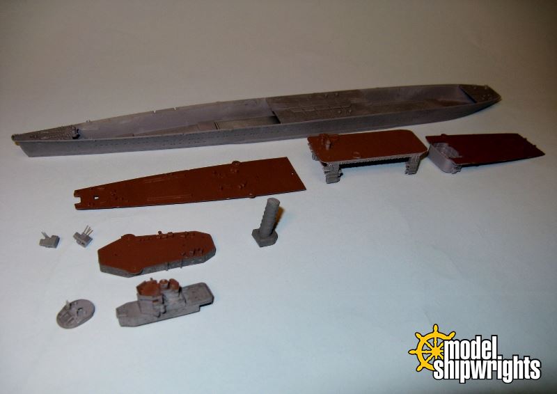
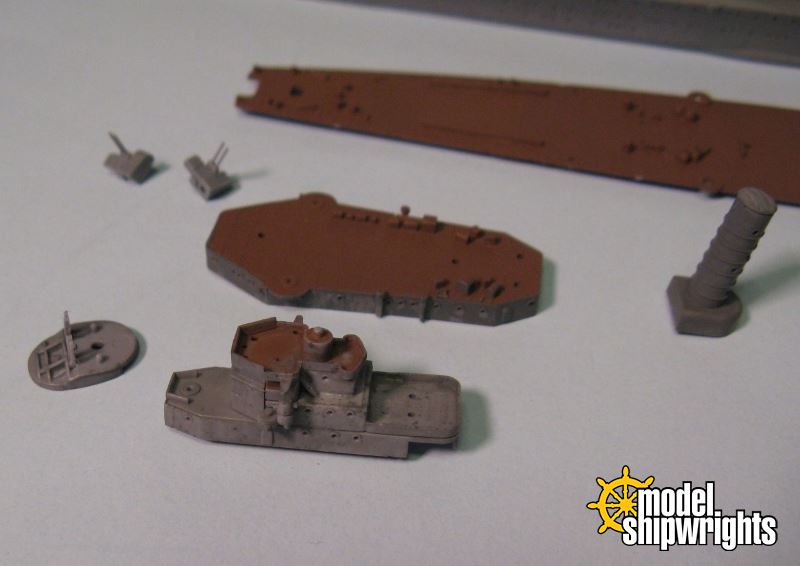
After the towers and elevated deck are attached, the major ship structure is complete. Now comes the “fiddly” parts. Cranes, catapults, antennas, parevanes, light flak guns, masts, search lights, launches – dozens of items.

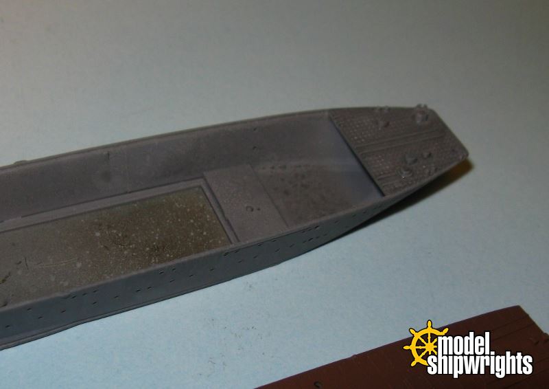
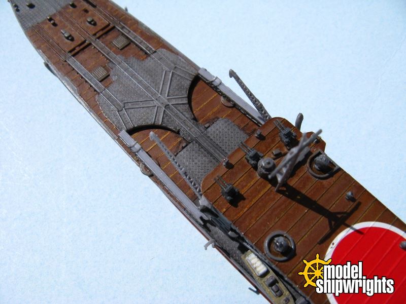
Many of these parts are very tiny and delicate. I did not follow the steps in the instructions religiously as I would have had trouble holding the model. So starting at the bow and moving aft, attach the 16-petal chrysanthemum emblem, kiku mon, symbol of the Japanese imperial house, followed by the foremast.


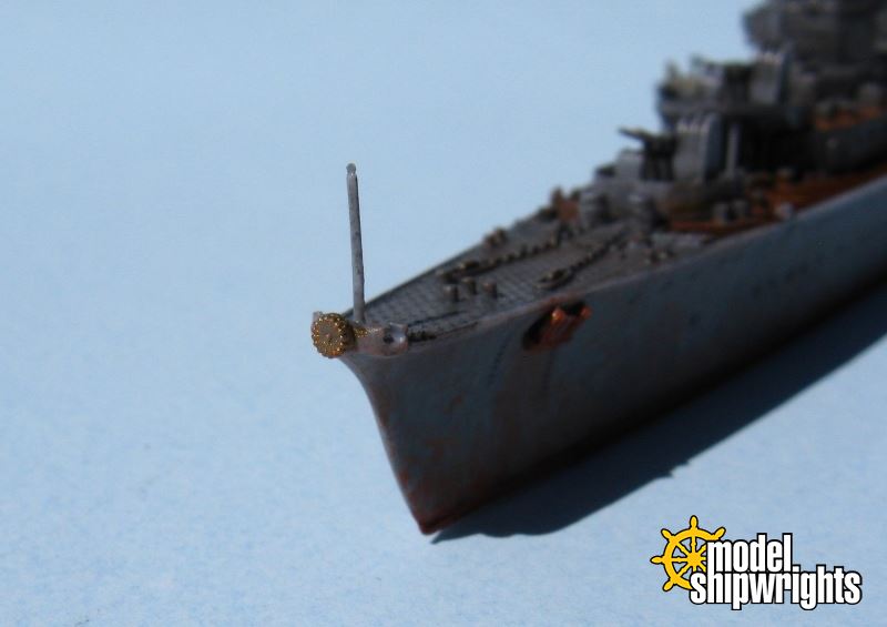
Oh, and I didn't forget the anchors!

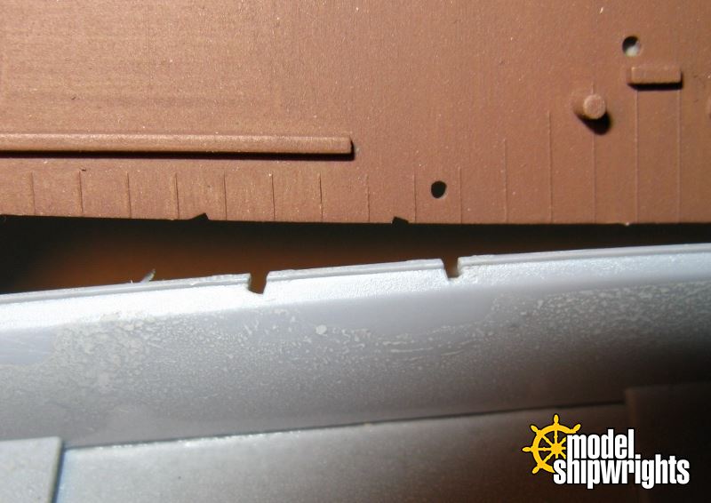
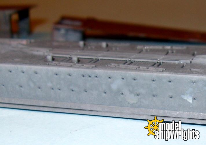
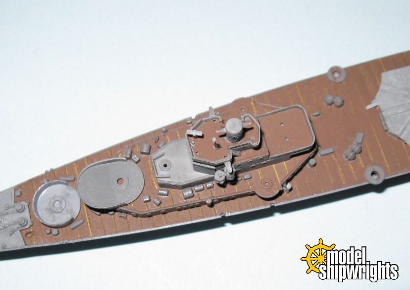
The Type 89 guns and mounts have been installed so I mounted the 25mm AA guns on the forecastle along with boom cranes. This is also when I attached the davits holding the 9m cutters to each side of the gunwales. These davits have generous tabs which fit into slots molded into the ship sides and weather deck.


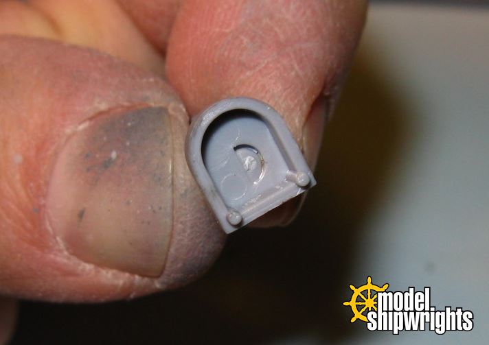
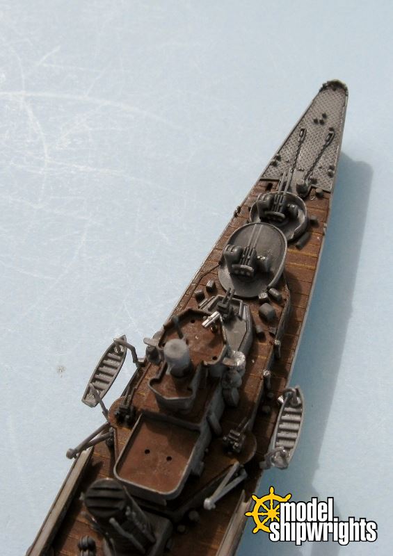
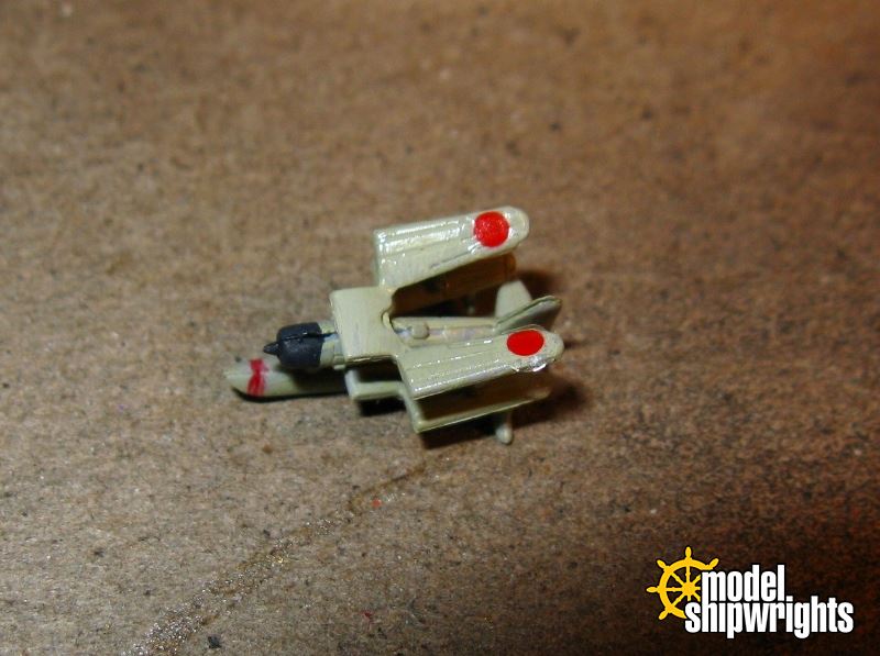
Next I moved up to the top of the superstructure to the flying bridge and finished adding the very tiny items (pelorus & binnacle?), including the searchlights. Just how small are those pieces? Take a look!


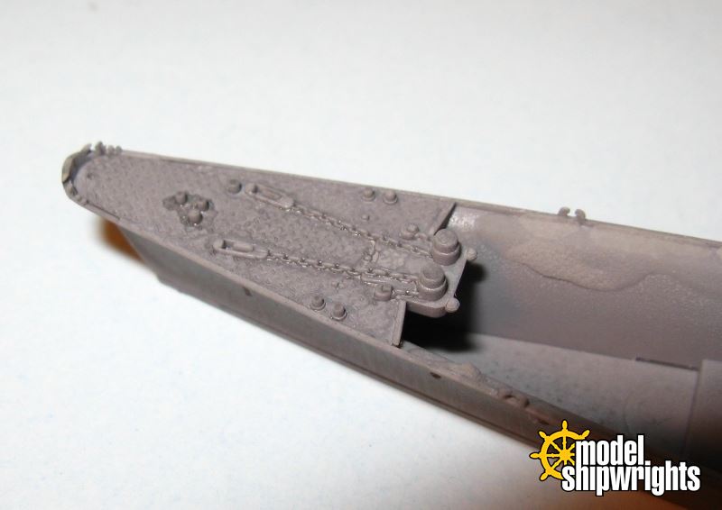
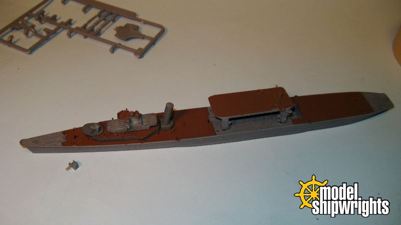
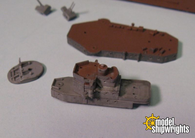
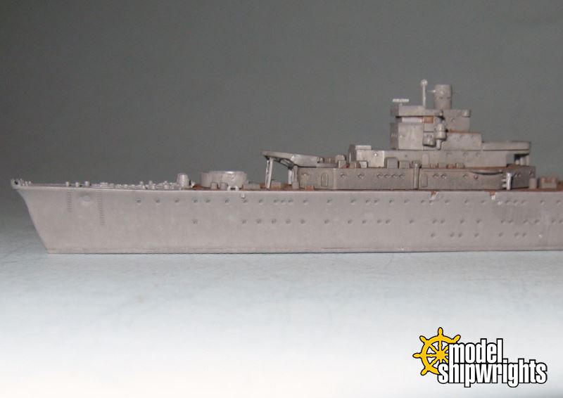
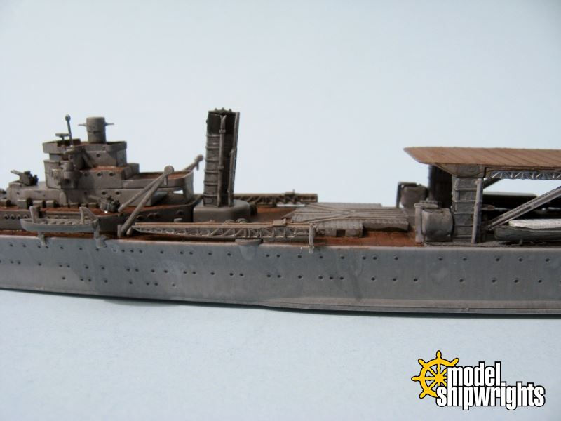
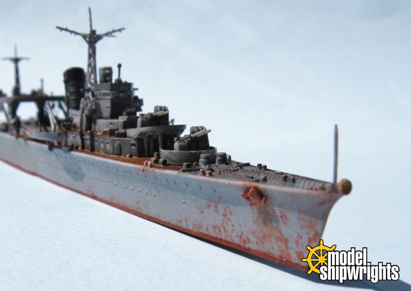
Two paravanes are secured to the deck on both sides of the stack. After all of the above is added, 
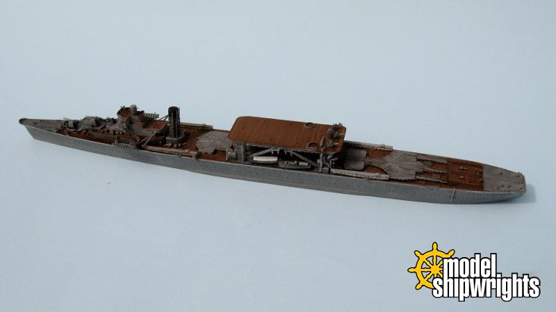
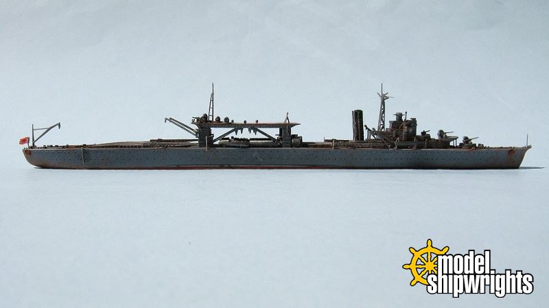
Chitose is starting to look complete!


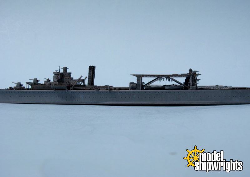
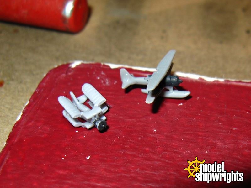
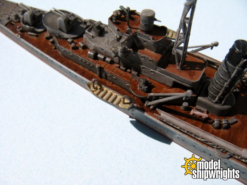
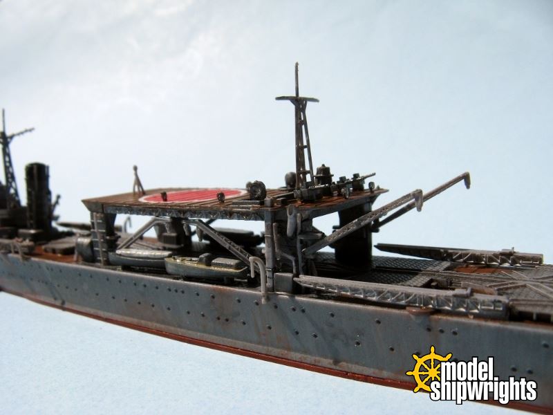
Now I attached the masts. The mainmast is five fine pieces. One part is the first I broke, a small V-shaped support for the yardarm. I pirated a similar piece from all of those wonderful small parts left over from the Aoshima I-365 sub kit! This image is also a good view of the stack. Four separate fine pipes run up the stack, attaching via their tabs into holes in the stack. Maybe it was the late of the evening but those little parts were an absolute challenge to mount and secure. They are meant to hang away from the stack, yet they kept trying to fold flush with it.


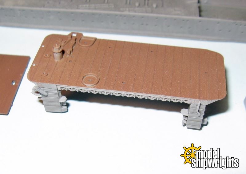
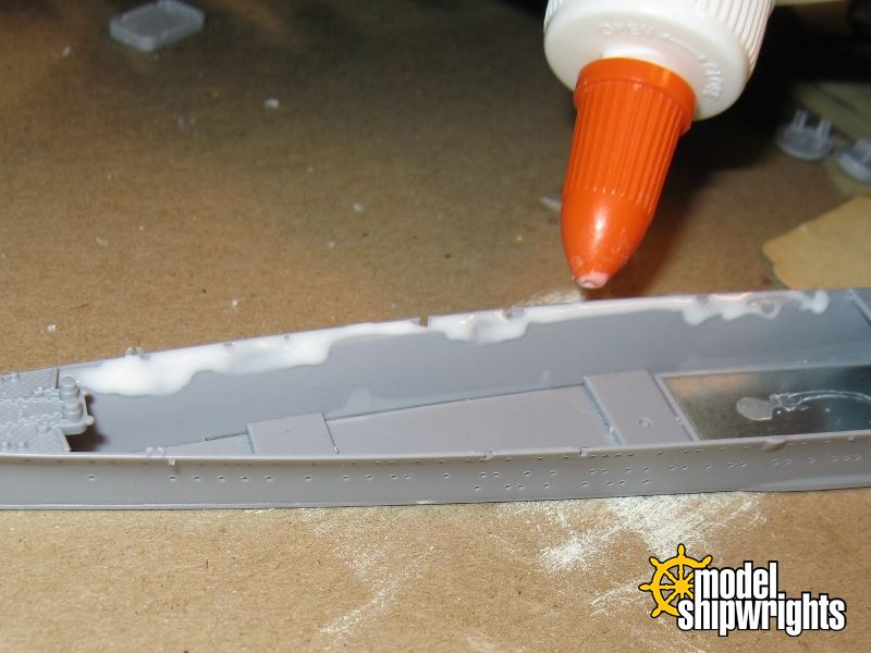
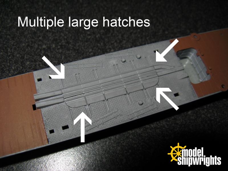
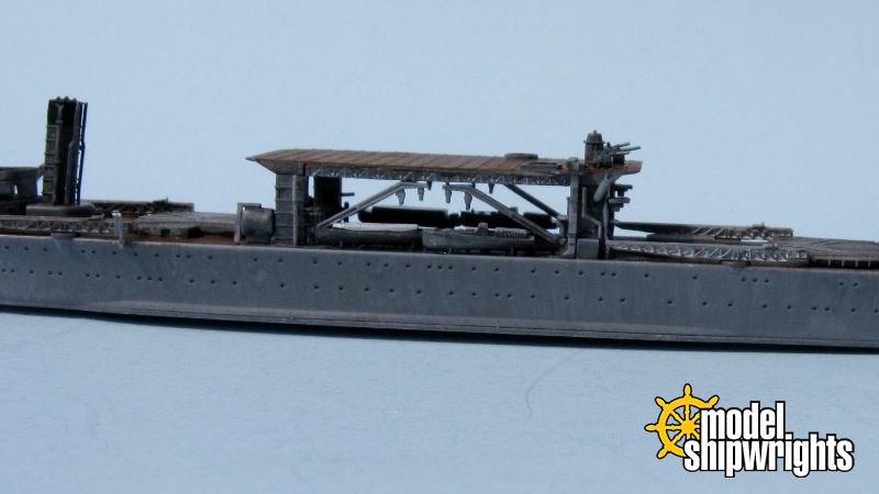
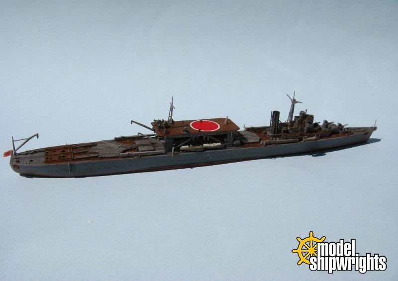
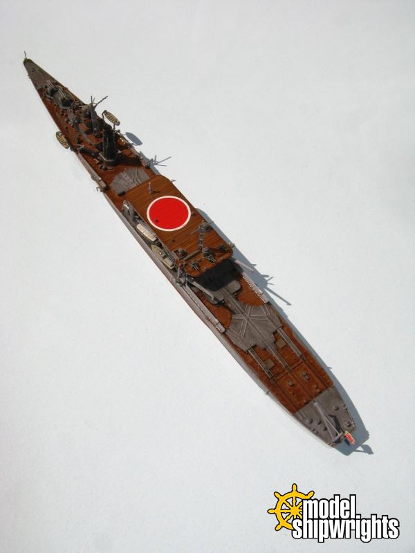
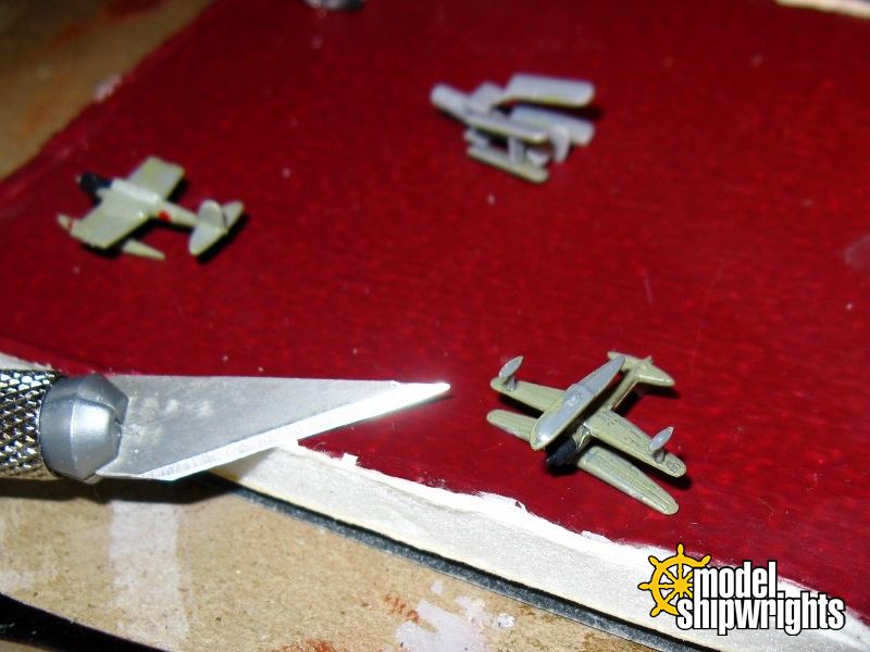
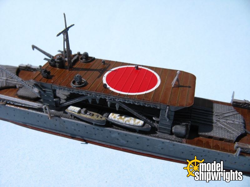
Moving amidships I focused on installing the remaining cranes and launches between the weather deck and elevated deck. With the Hinomaru adding a touch of color, the deck is ready for the final parts. The following image also clearly reveals the molded detail of the cranes, as well as the lack of open air in the rear mast assembly. Try as they might - and they are fine - Aoshima just could not get those pieces small enough.


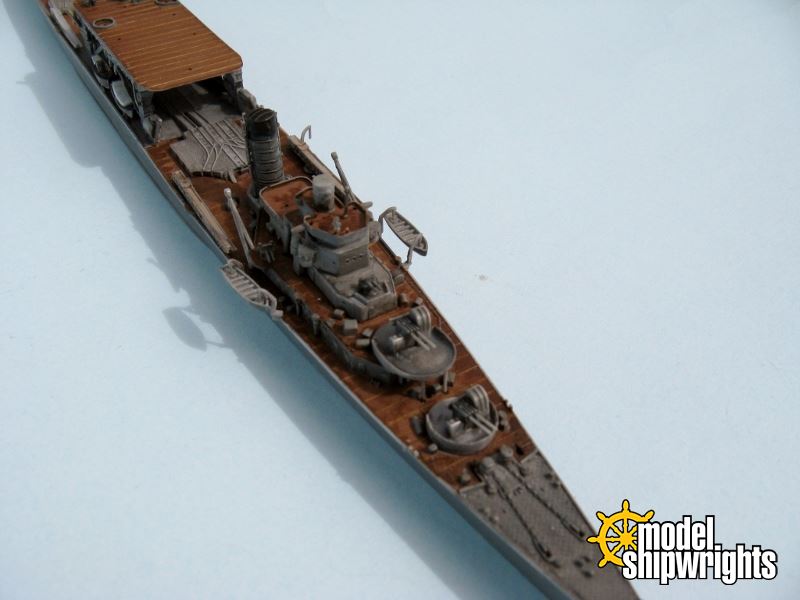
Two large searchlights and five small lights mount into holes in the upper deck. Again, just how small are the small ones?

The lights were easy to paint - just keep them on their sprue and pass a brush of ship color across the sides, top and back, leaving one face untouched. The clear styrene looks like glass. I did not get too fancy like I do with aircraft landing lights, e.g., paint them silver and then cover that with the exterior color. The small two-part DF antenna is attached. Be wary - the pieces are so thin and delicate that they bend. After the CA dried, I noticed it set at an angle. Regardless, this area is becoming ship-shape!


Not much is left abaft. I added the stern mast and another crane.


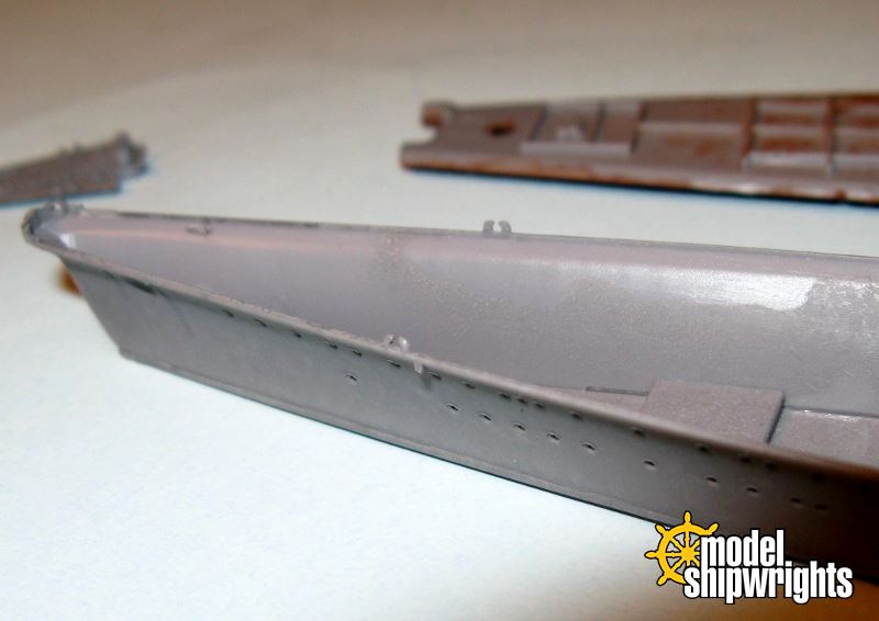
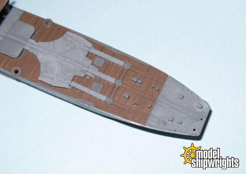
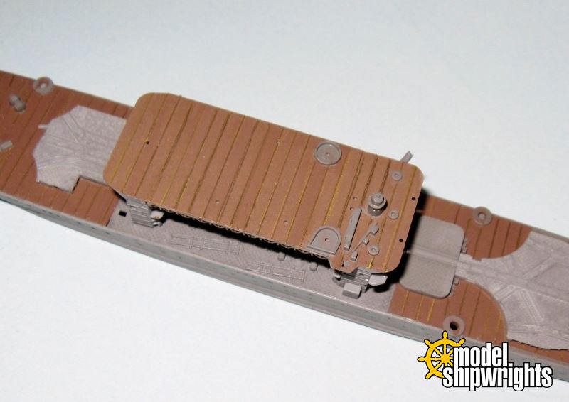
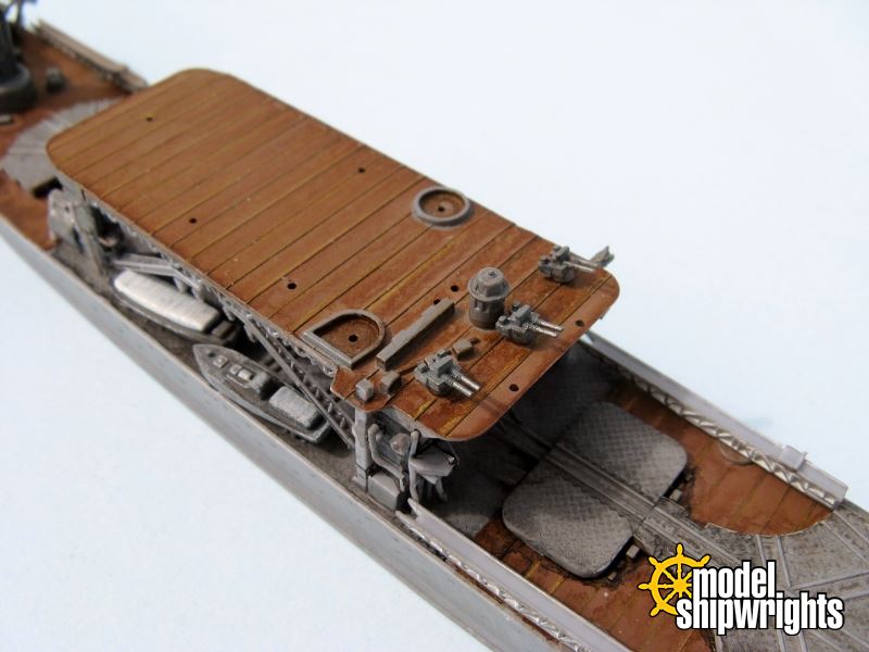
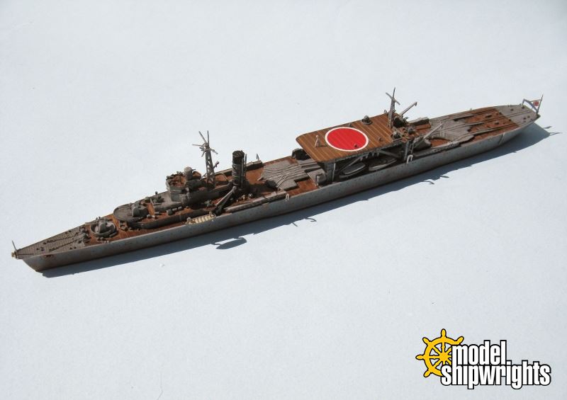
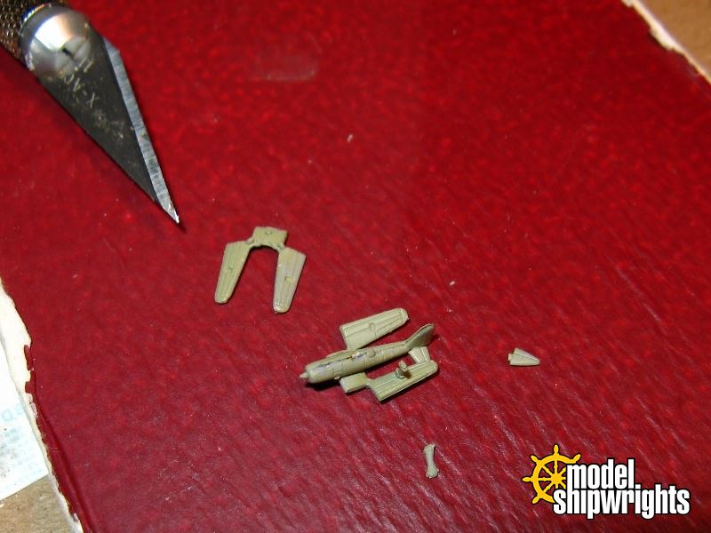
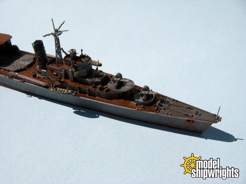
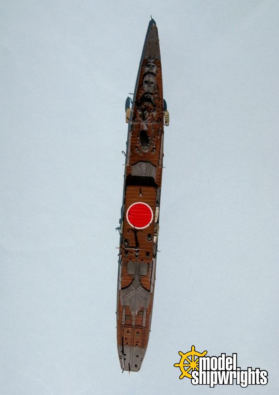
Before adding the parts atop the elevated deck I attach four widely spaced davits. These have no slots to mount them into. Almost imperceptible marks are molded on the ship sides below the gunwales. One must simply glue them and attach them butt joint style. They are very small parts. I lost one while cleaning the sprue burr from it. Thus, I did not de-sprue the other, instead I used two different davits from another it. These four parts are spaced wide enough that handling the model is not risky, just in need of awareness. You can spot those little rascals in this dive bomber-view.


The final touches next!
JPTRR
Staff MemberManaging Editor
RAILROAD MODELING
#051
Visit this Community
Tennessee, United States
Joined: December 21, 2002
KitMaker: 7,772 posts
Model Shipwrights: 476 posts
Posted: Friday, March 21, 2014 - 03:31 PM UTC
The parts are dry. Painting has been touched up and weathered up. I tried something new - counter-shading the catapults and cranes. I made both sides an off-white; I plan to repaint the sea-side a brown to simulate looking through them at the brown decks, yet leaving the inside white to simulate seeing a brighter ocean view. The entire model was hit with a dull clear. (Actually, I did so before attaching the searchlights on the raised deck - we don't want them frosted over, do we?)

So the clear parts went on. The last piece was the single-piece clear part of the wheelhouse windows. It is supposed to be mounted in the very first assembly step of building the bridge. I put it on now to protect it from paint and clear coat. It has miniscule framing to paint. I did it. Several times. Tiny framing! However, this piece is beast to insert into the cleft of the bridge! (Probably why one is meant to attach it in the very first sub-assembly of the first step.)

I am glad I did not because it is too thick and I suspect it would have prevented the wheelhouse roof / flying bridge (part A14) from setting flush.

Clear styrene tends to be brittle and a wing of this flat-bottomed "V" part broke. Then while I sanded it to fit into the bridge, it broke again. Eventually I managed to get the parts together and into the wheelhouse. I secured it with Future floor wax.

That's it. Chitose, the ship, is complete!


I wrote Chitose the ship is complete. The kit is not: the aircraft are still in progress.

Check back!
JPTRR
Staff MemberManaging Editor
RAILROAD MODELING
#051
Visit this Community
Tennessee, United States
Joined: December 21, 2002
KitMaker: 7,772 posts
Model Shipwrights: 476 posts
Posted: Thursday, March 27, 2014 - 04:18 AM UTC
Hi folks,


Ok, I just lost over an hour's worth of writing up the building of the airplanes. So until I am willing to start it again, I present the in-progress pictures:

phantom_phanatic309
#372
Visit this Community
United Kingdom
Joined: March 10, 2010
KitMaker: 2,568 posts
Model Shipwrights: 220 posts
Posted: Thursday, March 27, 2014 - 09:15 AM UTC
Fantastic build Fred. Its a fine looking ship, I might just have to get myself one. How did you paint in the brass deck bands? This is is something I've found tricky to do neatly on Japanese ships.
Those little planes are a lot of fun to build and paint. I've just gotten a box each of Trumpeters Corsairs, Avengers and Walrus to use on my planned build of HMS Victorious as she looked in the Pacific. I'm amazed at the level of detail that can be gotten on them now.
JPTRR
Staff MemberManaging Editor
RAILROAD MODELING
#051
Visit this Community
Tennessee, United States
Joined: December 21, 2002
KitMaker: 7,772 posts
Model Shipwrights: 476 posts
Posted: Thursday, March 27, 2014 - 06:38 PM UTC
Hi Stephen,

Thanks for your encouraging words.

I used a Prisacolor gold pencil for the bands. Keep the tip sharp and gently run it atop the raised bands. The color core "lead" is soft so I had to rotate it frequently. I tried a number of artist markers, even down to .5 mm; too big and too eager to squirt paint all over the model. Perhaps a feather touch could pull it off, I couldn't.

Yes, the level of detail on these little airplanes is fascinating. I have re-written my assembly of them, posted below. All those little parts and difficulty in handling them tanked the fun meter. They passed from fun into the realm of no inanimate object is going to beat me!
JPTRR
Staff MemberManaging Editor
RAILROAD MODELING
#051
Visit this Community
Tennessee, United States
Joined: December 21, 2002
KitMaker: 7,772 posts
Model Shipwrights: 476 posts
Posted: Thursday, March 27, 2014 - 06:50 PM UTC
Airplanes Chitose is complete but the kit is not until the aircraft of her Kōkūtai are. Your deployment of Chitose is dated by the aircraft embarked. I assembled each of the four types to because they are part of the kit. The following is my experience with assembling the model aircraft.

To create her Kōkūtai three sprues are included: two-each of sprue W (The 1994 issue of capital ship “Levianthan” equipment.) and the new sprue (Nr. 12-1517, date undetermined) "Air Plane" [sic]. The sprues each hold a single “Alf”, “Dave”, “Pete”, and “Jake” floatplane.


Sprue W airframes are molded as a single piece for the fuselage, lower wing, and empennage. They have good sharp basic detail. Upper wings and floats and outriggers are separate. The aircraft have their wings extended for flight. Like all 1/700 aircraft of the era that I know of, no interplane struts are included.

Sprue Air Craft is remarkable! Except for the relatively simple monoplane “Jake”, all aircraft are mini-kits themselves. The Type 94 is the simplest biplane with merely 10 parts, the breakdown for each type being:
* Left and right fuselage halves
- Separate Lower wings
* Separate Upper wings
- Individual floats and outriggers
* Separate horizontal stabilizers
- Separate interplane struts


These four aircraft are unique in that they are molded with their wings folded. Aoshima even simulated the angle of incidence and dihedral. Molded detail is equally impressive with panel lines, faux fabric covering, control surface demarcations, and brackets for the struts. The only components missing are the propellers.


I give Aoshima an A for effort. These miniscule pieces are probably at the limit of practical and affordable 1/700 injection molding technology. The struts are fascinating and molded with daylight between the struts yet tiny as they are, they are overscale. Still, I appreciate them and think they look better between the upper and lower wings than the void common to other 1/700 biplanes. If the bulk troubles me, I will acquire the photo-etch set.

Amazing as those aeroplane models are, assembling them requires the patience of Job! The challenge is that all of those pieces are so small and slippery that they are difficult to grip and hold, even with needle-nosed tweezers. Probably half of my assembly time was simply trying to take – and keep - hold of the teeny parts! I suggest working with them in an enclosed area like a bowl or box. These parts are elusive. I feel fortunate that I only lost two pieces. Unfortunately one piece is significant - an interplane strut for the Kawanishi E7K2. The other is a wing float for a "Pete". Time to stretch some sprue….

Aoshima tooled the fuselage halves to line up via conventional peg/slot method, and they are tiny. While the fuselage halves were cleverly engineered so that the sprue attachment point does not contact the exterior of the fuselages, the attachments span over into the solid interiors. Precise cleaning is required and if even a bit remains, it will cause the fuselage to be catawampus or suffer noticeable gaps. Each fuselage belly has a shallow depression into which fits the center section of the lower mainplanes. These depressions are too shallow and must be carved or filed out lest the wings noticeably extend from the fuselage. Align these parts carefully.

Aoshima did a commendable job molding locating holes in the fuselage for the stabilizers and floats and struts. I was happily surprised that the tailplanes - even without mounting tabs – fit so well to the fuselages. Align them carefully. Unfortunately, one two of the airframes the lower wing tips are too high and conflict with the horizontal stabilizers. More about that to follow. Aligning the outrigger floats laterally, longitudinally, and vertically while the glue sets is torturous.

Mitsubishi, Nakajima and Kawasaki designed their respective floatplanes with wings that folded back along the fuselage, via pivots on the trailing edges. Those pivot points are incredible small and the angle of incidence and dihedral of the wings are very susceptible to distortion. The diminutive interplane struts must be solidly attached with great finesse in alignment; even when they are the outer wings are held to the center section by a wisp of plastic and flex. This greatly complicated the mounting of the upper wings to the struts and to the fuselage.

More soon!
Shanghaied
Visit this Community
Schleswig-Holstein, Germany
Joined: June 30, 2011
KitMaker: 189 posts
Model Shipwrights: 106 posts
Posted: Friday, March 28, 2014 - 12:39 AM UTC
What a pity they do not make a Chitose in 1/350. Your work is great, but the scale is too small for me

Greetings from Shanghai
JPTRR
Staff MemberManaging Editor
RAILROAD MODELING
#051
Visit this Community
Tennessee, United States
Joined: December 21, 2002
KitMaker: 7,772 posts
Model Shipwrights: 476 posts
Posted: Friday, March 28, 2014 - 09:37 AM UTC

Quoted Text

...but the scale is too small for me


Hi Shanghaied;

Maybe for me, too! I am enjoying the bigger scale more. Too bad I haven't the space.

The air group is shaping up:


I'm prepping for a Guadalcanal era. "Alf" and "Dave" are being built for earlier.

That tip-float I lost? I made one with sprue:


I also made the "N" strut for "Alf". Pics to follow!
phantom_phanatic309
#372
Visit this Community
United Kingdom
Joined: March 10, 2010
KitMaker: 2,568 posts
Model Shipwrights: 220 posts
Posted: Friday, March 28, 2014 - 11:19 AM UTC
Prismacolor pencils! Why did I never think of using those? I used to use the silver for doing light paint shipping and found it easier and more controllable than drybrushing. I'll have to keep my eyes open for some next time I'm near an art shop.

The aircraft look great, the hard work has paid off.

 _GOTOTOP