Hello Again!
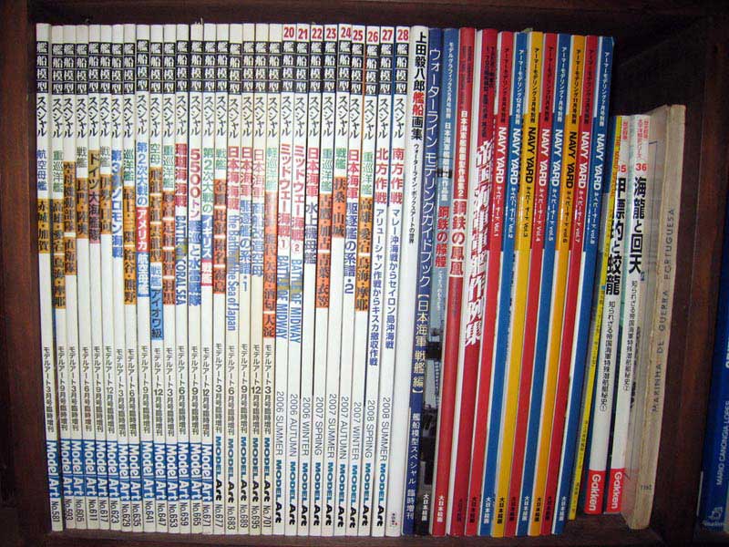
Here is a sample statement from my recent translation work for Model Art #24 special.
Again, the full text is available from Pacific Front Hobbies.
FUSO FINAL STATE 1944
What I worried about in the assembly was the attachment of the lower part of the rear mast (5) to the deck but, what did not go very well was the insertion of the polycap used for rotating the main guns. Other than these the joining was good such that the majority went straightforward. The joint of the crane motor room (8) with the linoleum deck (3) would make the sides of the deck jut out a bit. In this example it was shaved off, with the joint becoming one surface the surface management was conducted. Furthermore by re-verifying the photos of the electric motor room, an protrusion can be seen, perhaps the single surface is probably an error. Be careful about removing the indicator for attaching the auxiliary gun tracker on the rear mast (7). Two of the reserve command post (K2) was attached to the sides of the bow.
Adjusting the Outrigging
Please note the part numbers for the main and auxiliary anchors are reversed. The portside of the lower part of the bridge (39), was filled up with plastic material and the adjustment to the shape was carried out. On the molded turntable, since the rails were not represented, the surface of the turntable was thinned down and the rails were represented by gluing on plastic materials. Furthermore in this example a process was done to join with the height of the molded rails but, the molded rails were slightly lower such that even the rails had to be remade for more realism. Even while indicated for attaching the twin mounted 25 mm machine guns, four of them on top of the number five main gun and on the front of the bridge structure, note that they were triple mounted guns.
Year Modification
The combat bridge (37) had the deck widened by using plastic materials (0.5 mm thick). At that moment some of the bulwark was shaved away. Also since the deck for the anti aircraft command station was widened (21), plastic material was used in the same manner, the deck and bulwark were reproduced (this also was pleasing as there were two types like the range finder). The number of portholes on the hull were molded on since it was in the state before it was covered up by combat experience, only the upper most on the sides of the bow remained, other than that all of them were filled up. When doing this process, the joint molded on and the monkey-ladder were completely removed such that in this example these were resolutely shaved away.
Exchanging the Outrigging
The 21-go radar (65) was substituted with etched parts. Furthermore the etched parts were simple to assemble through the assembly directions. The searchlight support (60,61) were exchanged for the etched parts. Furthermore the passageway that bind the front and back was represented by cutting away the kit parts. Additionally the support for the machine gun stand (lower side of the forward searchlight stand) that was molded on was shaved off, represented by etched parts (it was necessary to adjust the height). Furthermore, as for the year of production since it was possible to install the radar room with removal of the searchlight (numbers 1 and 2), it was fine to have this reproduced. The etched parts were used for the shield used for the twin and triple mounted 25 mm machine guns (above wooden deck) (64). Two types of twin mounted 25 mm machine guns were prepared (1) and (W41) but, in this example all of the latter were attached (these were more smaller). The top mast for the upper part of the rear bridge (9,11) were substituted by brass wires (0.3,0.4,0.5mm diameters). The crane (10) had the arm section substituted by the etched parts. Additionally the catapult as well (W44) was substituted by etched parts.
Additional Outrigging
The fairlead was reproduced by being molded on but, as such it was thin so CSI Creos Mr. Surfacer 500 was filled in to increase the volume (only the bow and stern). The outer electrical wiring was represented by making small cuts of masking tape and pasting it on (the layout is an assumption). Furthermore the adhesive for the tape was weak such that it was made sturdier by flowing on cement. Also the tapes surface as such was sticky, the surface was adjusted by a coating of Mr. Surfacer 1000. Three assemblies of the boat davit (W23) was both sides each, represented in the stowed position. One loop antenna was installed on top of the protrusion on the side of the bow at the air defense command post (W42), on top of the protrusion on both sides one each of 22-go radar (W1)was installed (stern side). One each of 13-go radar (Pit Road accessory set E2) was installed on both sides of the funnel.
On each searchlight stand (51, 54, 56) the bulwark was molded on but, the section in this instance since having a hand rail, in this example it was shaved off. Furthermore this bulwark section was painted in white color, so that it could represent the canvas extending over the hand rails. The support for the cross tree on the rear bridge (K3) (actually wide wire perhaps) was represented by brass wires (0.3mm diameter). The wire for the crane used for the seaplanes and derrick (13) was represented by loose lead wire (most effective economically). The single 25 mm machine gun stand on top of the number 3 and 4 main gun turrets was represented by plastic materials (0.5 mm thick). The single mounted 25 mm machine guns (Pit Road accessory set E10) as for the time of production there were 39 of them installed (including five units that had been moved) but, in this example 34 of them were installed with the moveable ones omitted (some of the positions are presumptions). The shape of the twin mounted 25 mm machine gun stands on top of each of the main gun turrets (2 right, 2 left) varied according to the materials. Since the actual one is not clear in this example it was used as such but, the fussy people it is fine to repair this. The ten 13 mm single mounted machine guns were installed at the time of production but, in this example they were left off.
Painting
For the exterior color Kure navy arsenal color (Mr Color warship color set 1 (SC01) was used. The reason for choosing this color was that it was because it was being docked at Kure Arsenal somewhere between August 2 to August 14, 1944 before taking part in this operation. The wooden deck since it was exposed to the environment where the wood was becoming older as it was used, to a 1:1 mixture of Sail Color (45) and Dark Sea Gray (25) 10 percent of matte white (62) was added in for the color tone and then painted on. The color of other sections were the lower part of the draft line was painted in hull color (29), linoleum deck (warship color SC06), the upper part of the funnel and middle of rear mast was painted in matte black (33), each of the gun turret water proof canvas and motorized launch canopy were painted in Grand Prix white (69), the inside of the cutters painted in wood brown (43), the body of each machine gun, upper surface of transport rails, wires were painted in black metal color (28), the Imperial badge in titanium gold (Tamiya Acrylic X31).