

Go to modelshipwrights.com for the current dynamic site!


1⁄350USS Lexington (CV2) 1927-1942
23
Comments
Stage 17: 5-inch fire control
Kit parts: 8
Scratch parts: 76
PE parts: 8
Time: 6.25 hours
There were four 5-inch fire control stations, port and starboard on the foretop and on the upper platform at the aft end of the stack. Each controlled one of the four groups of three 5-inch guns. Unlike later fire-control systems in which the director and range finder were combined in one unit, in the Lexingtons these functions were separated. The Mk19 directors (target bearing and training) were located close to an associated rangefinder/altimeter (range/altitude and laying) unit. Clearly this close proximity was essential to ensure both teams were concentrating on the same target. Quite erroneously, the Trumpeter kit omits the directors completely, their positions being occupied by light AA weapons.
As you would expect, the 5-inch fire-control fittings on the foretop and on the stack platform were identical. But for some inexplicable reason, the aft rangefinder platforms and shields (parts D22 on the instructions but actually F22) are much smaller in diameter than their forward counterparts (E6), and neither do they have the correct stepped profile. And given that the shields were actually rails covered by canvas dodgers, the best option was to make up all four of these from scratch.
The rails were made from three-bar rail with the lower rail removed, and the upper rail removed at the ends to give the characteristic stepped-profile. These were fixed to circular styrene platforms and the effect of the canvas dodgers created by in-filling the rails with PVA glue.
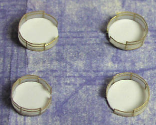
Above: rangefinder platforms.
The directors were mounted on tall pedestals with circular wooden gratings for the fire-control team to stand on when operating the director. Each pedestal was made up from a piece of circular styrene sheet (the operating platform) mounted on a length of styrene tube. Two-bar railings had splinter mattresses attached to them. Note that the railings surrounded only half the operating platform on the forward directors, but on the aft directors were continuous apart from an access opening.
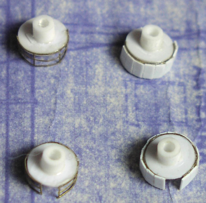
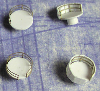
Above Director pedestals.
The directors supplied in the kit are very accurate representations. The pedestals had to be reduced in height. There were two telescopes on the rear (one each for the layer and pointer), and one on the left hand side (for the cross-level operator). These were made from very thin stretched sprue inserted and glued into drilled holes.
The rangefinders are not very accurate in their detail. I considered scratch built replacements, but decided the scale is simply too small to make this worthwhile. Instead I adapted the existing parts. The over-scale end caps were reduced in size and the central dome removed. This was replaced with a short vertical length of rectangular section styrene representing the base of the height-finding unit. To the rear of this and off-centre, a length of vertical styrene rod represented the height-finding tube. The rangefinder pedestals were too high, but there had to be a secure way of fixing them into the deck. I left the mounting spigots in place but sliced away the circular bases above them. This allowed me to insert the units into the deck with adjustment for height.
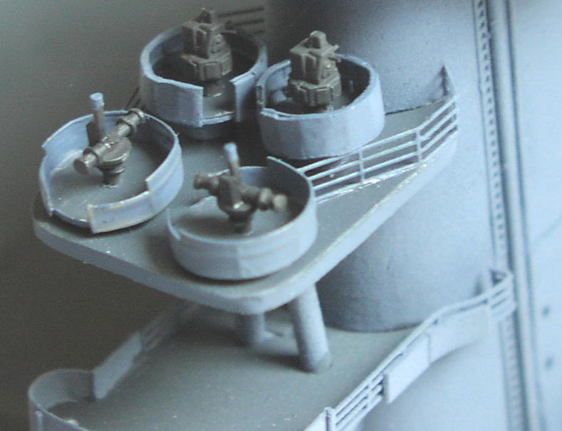
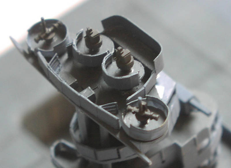
Above: Completed 5-inch fire control on foretop (left) and aft end of stack (right).
Tip from experience: To airbrush paint these small items, apply double-sided adhesive tape to a piece of scrap wood, styrene sheet, or whatever comes to hand. Put the items to be sprayed on the adhesive tape. They will stay in place and can be easily removed afterwards.
Stage 18: flight deck and hull assembly
Nautilus parts: 2
Kit parts: 1
Scratch parts: 8
Time: 5.25 hours
The Nautilus laser-cut wooden flight deck developed a serious distortion after Id removed the two pieces from the panel. The edges along the length bowed upwards. To correct this is I glued suitable lengths of sturdy balsa wood stiffeners to the undersides. I used PVA glue for maximum strength and clamped the stiffeners to the flight deck panels while the glue cured. One of these was positioned to act as a supporting bridge between the two sections.
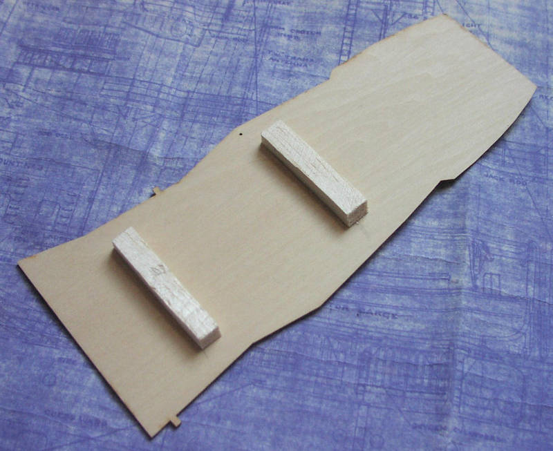
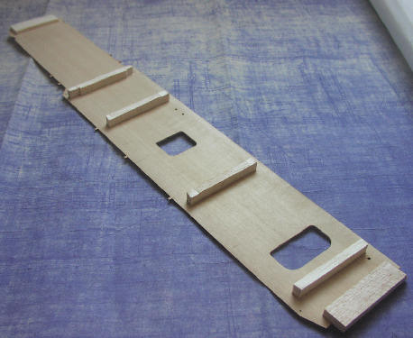
Above: Reinforcing the flight deck to prevent warping.
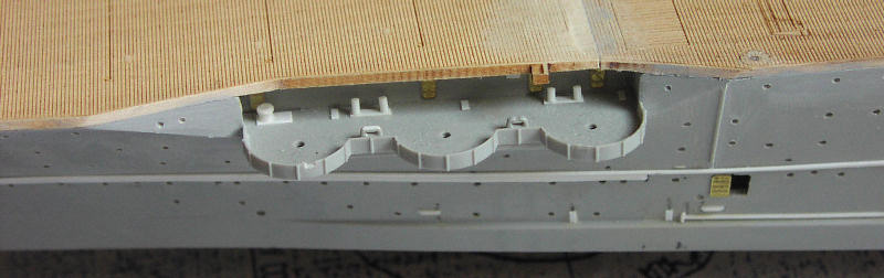
The forward edge of the flight deck was sawn off the moulded flight deck part in the kit and cemented to the bow. The aft round-down had already been similarly sawn off and cemented in position as part of the aft deck assembly stage. For some odd reason, the forward flight deck in the kit and the Nautilus equivalent is very slightly wider on the port side than the starboard side. I can only presume that Nautilus followed the outline of the Trumpeter part in order to create a matching like-for-like replacement. It should be symmetrical, but visually this error is not intrusive and is easy to live with. But do make sure the forward edge is positioned laterally so that it aligns with the flight deck.
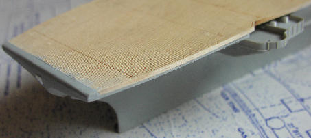
Above: Integrating plastic and wood at the forward end of the flight deck.
Attaching the Nautilus deck to the hull was where things got really interesting. Allow a good hour for this job. I dealt with the aft section of the Nautilus deck first, saving the forward section later for adjustment and fettling. I had assumed that the issue was going to be ensuring the flight deck attached to the hull in all planes in a vertical direction. Initially I assembled a collection of kitchen scale weights to bear down on the flight deck during the gluing process. I then decided it would be better to invert the hull on a level surface and apply the weight to the hull cross-members.
When it came to the job, this really wasnt the issue. Instead, it turned out to be ensuring that the edge of the hull matched the edge of the flight deck. Having applied medium thickness superglue to the hull edges and put the aft section of the Nautilus deck in place, they didnt match up. But which was correct the hull or the flight deck? The hull could be squeezed in or pulled outwards. The flight deck could not. I worked through this on a visual rather than scientific measurement basis as the superglue was curing. The objective was to ensure the hull was spread or squeezed to match the edges of the flight deck where possible. The flight deck overlapped the hull in places, which was fine because that would only involve subsequently removing material. What was not tolerable was having the hull extending beyond the edge of the deck. Such is art and modelling convenience - over science.
Blending the deck edges into the hull profile was important and worth spending time on getting right. I have seen at least one completed model of this kit on the Internet where the deck looks exactly what it is a separate plank of wood stuck onto the hull. It was a repeticious process of sanding, filling, sanding, filling and sanding again until a fine blend was achieved without any gaps.
Above: Its worth spending time ensuring the edge of the flight deck is flush with the hull.
About the Author


FROM: ENGLAND - EAST ANGLIA, UNITED KINGDOM
1966-1971: Art college in Twickenham and Blackpool 1971-1973: Commercial art studio, Ipswich, Suffolk 1973-1975: Philips, Eindhoven, Netherlands 1975: Lecturer Ravensbourne School of Art, Bromley, Kent 1976: Marketing Communications, IT systems and software house, London. Got married...
Comments
Hi Joseph,
Yeah, it was a lot of research. I was DETERMINED to make it abolutely as accurate as possible. What I don't understand is how Trumpeter got so much of it grotesquely wrong. Anyway, thanks for your comments. I sure hope you find my feature useful - from what I've seen the 1:700 from Trumpeter is just a scaled down version of the 1:350 kit, including everything that's wrong with the big one!
JUL 08, 2008 - 05:36 AM
Hi Rui
Well, well, well. I used to be a graphic designer myself as well. And a copywriter. Hence what I hope is a deal of professionalism in my SBS guide.
The whole project spanned two years. I didn't dare start another model in all that time, knowing it would simply delay completion and possibly I would lose my motivation. Sometimes it was very hard to keep going - the progress when doing the armament and the air group seemed so slow. I really had to force myself to keep going.
Thanks for the advice on using Clearcoat on the decals. Actually, that is what I did use, in order to soften the decals so they would lay close on the curved fuselage sides, to get them to stick, and to try and dull them down. All the planes were matt varnished as well, but that still didn't kill the decal edge reflection.
You can see some of my 1:700 stuff at: LINK If you select my name from the top of the menu on the left you can see all my galleries.
By the way, the 1:700 Trumpeter Lexington looks like just a scaled-down version of the 1:350 version, including everything that is wrong and inaccurate. So please, please, do use all the research I did to get it right. I look forward to seeing the result!
Regards, Chris
JUL 08, 2008 - 05:48 AM
Jim
Your comments an honour indeed. I have followed your work over the years at Modelwarships.com and you really are the best. Counting the hours is actually a way of giving myelf a sanity check! Which is why to some extent the whole project took me two years from start to finish.
Regards, Chris
JUL 08, 2008 - 05:53 AM

Thanks for taking time to answer to my questions!
I have the 1/700 Trumpeter model, for Coral Sea fit, so I guess you have done all the research for me - but still, I have to get the work myself!
Not for now, but for a "near" future (I am currently working on three projects, one a full scratch all in 1/700).
Thanks for the link, and since my memory is better for graphics, than for names, I can say that I had already seen your Sara / Lex duo in MW.
Please keep up - keep your ship models afloat!
Rui
JUL 08, 2008 - 05:57 AM

Are you sure that thing is a model. It looks so real. In some of those photos it looks too real. Nice job. Amazinglly nice job. Great tribute to those who sailed, fought and died on board the original Lady Lex carrier. Nice work.
JUL 11, 2008 - 08:46 AM

Hi Chris,
Sorry no plans on any new 1/350 items.
You could use my YC-728 or 829 for an open ammunition lighter. I have some photos of their use as such.
JUL 15, 2008 - 07:06 AM

Hello Chris:
I just finished reading your build log. Outstanding work and very well written. I have this kit, not sure I want to tackle all the inaccuracies vice just building an OOB kit, but, your work is inspirational and you presented a lot of neat ideas to enhance the kit. I will be referencing your build log when I tackle mine. Thanks for posting and sharing.
FEB 10, 2015 - 08:49 AM

Mark, I doubt Chris will respond as this is a 7 year old tread and Chris last signed in 7 years ago.
FEB 10, 2015 - 09:13 AM

wow, awesome model building.
well worth resurrecting the thread and feature.
FEB 11, 2015 - 09:17 AM
Copyright ©2021 by Chris Smithers. _OPINIONS Model Shipwrights, KitMaker Network, or Silver Star Enterrpises. Images also by copyright holder unless otherwise noted. Opinions expressed are those of the author(s) and not necessarily those of Model Shipwrights. All rights reserved. Originally published on: 2008-07-04 00:00:00. Unique Reads: 23646

WEB HOSTING BY


Copyright ©2021 Model Shipwrights and Kitmaker Network, a subsidiary of Silver Star Enterprises
All Rights Reserved. Please read our Conditions of Use and Privacy Policy.
All Rights Reserved. Please read our Conditions of Use and Privacy Policy.