

Go to modelshipwrights.com for the current dynamic site!


1⁄350USS Lexington (CV2) 1927-1942
23
Comments
I constructed a proper bracket for the CXAM radar antennae from styrene sheet. This was modelled in the fashion of the bracket on the Saratoga for which there are ample photographic references.
Kit parts: 2
Scratch parts: 31
PE parts: 4
Time: 6 hours
The lower platform (D21) was discarded. The first reason for this was the illogical indentations on each side. I presumed that the makers of the kit had misinterpreted the dark area in this region shown in the final picture of the vessel intact at the battle of the Coral Sea. I think it far more likely that this visual effect was caused by the dislodging of the splinter mattress in this position from the shock of the previous torpedo explosions, or for some other reason.
The second reason for discarding it was that that it does not correspond with the plans of the ship or photographs. These clearly show that on the outboard side it extended around the rear face of the stack to a point close to the vertical ladder.
The third reason was that the locating holes for the vertical struts in the platforms are too far apart, although the strut spacing at lower deck level is correct. It is worth noting that the struts (D11 and D12) should be correctly orientated so that the tops are horizontal.
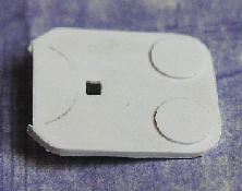
I made a replacement platform from styrene sheet, with semi-circular light AA sponsons incorporated at the rear quarters, and an open hatch giving access from the ladder below. Full bracketing (styrene sheet and PE) was built on the underside.
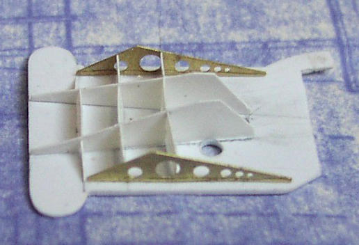
Above: Underside of lower stack platform.
To simplify construction and make a stronger joint - I sawed out the slot in the aft end of the stack into which I could cement the platform, rather than trying to cut an accurate semi-circle in the platform to match the slot.
There must have been problems with vibration of this platform because additional stiffening brackets and webs were added during the ships life. That includes parts D21 (and their PE equivalents) under the outer edges, and tall triangular webs located on the rear faces of the struts below the platform. The four bracing rods between the struts and the underside of the platform were made from thin brass wire. There is close-up photographic evidence of an additional small platform (below the erstwhile lower platform) added late in the ships life between the struts and the aft face of the stack. There were no rails or lifelines on this, and it may have been added for structural reinforcement reasons.
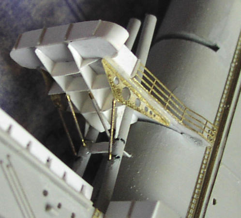
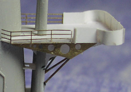
Above: Details of lower stack platform.
I fixed two splinter mattresses (suspended from the second bar) at the forward end of the rail on the outboard side. This left an unprotected gap of the same length of a splinter mattress before the start of the shielding, as described in the first paragraph of this section. I couldnt bear to continue covering up any more PE railing in this way, so didnt fix any splinter mattresses on the inboard side.
Scratch parts: 22
PE parts: 4
Time: 2.75 hours
The upper platform for 5-inch control (D22) was discarded because it is 3mm too narrow. That may not sound like much, but it translates into a 15 percent dimensional error that scales up to more than 1 metre. Furthermore, the raised platform at the forward end is irrelevant and there should be four (not three) longitudinal brackets on the underside.
Bracketing on the underside was constructed from styrene sheet and GM PE replacements for parts D24. As with the lower platform described above, to simplify construction and make a stronger joint - I sawed out the slot in the aft end of the stack into which I could cement the platform, rather than trying to cut an accurate semi-circle in the platform to match the slot.
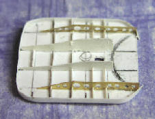
Above: Underside and top of upper stack platform.
Stage 15: Lower stack platform
Kit parts: 2
Scratch parts: 31
PE parts: 4
Time: 6 hours
The lower platform (D21) was discarded. The first reason for this was the illogical indentations on each side. I presumed that the makers of the kit had misinterpreted the dark area in this region shown in the final picture of the vessel intact at the battle of the Coral Sea. I think it far more likely that this visual effect was caused by the dislodging of the splinter mattress in this position from the shock of the previous torpedo explosions, or for some other reason.
The second reason for discarding it was that that it does not correspond with the plans of the ship or photographs. These clearly show that on the outboard side it extended around the rear face of the stack to a point close to the vertical ladder.
The third reason was that the locating holes for the vertical struts in the platforms are too far apart, although the strut spacing at lower deck level is correct. It is worth noting that the struts (D11 and D12) should be correctly orientated so that the tops are horizontal.
I made a replacement platform from styrene sheet, with semi-circular light AA sponsons incorporated at the rear quarters, and an open hatch giving access from the ladder below. Full bracketing (styrene sheet and PE) was built on the underside.
Above: Underside of lower stack platform.
To simplify construction and make a stronger joint - I sawed out the slot in the aft end of the stack into which I could cement the platform, rather than trying to cut an accurate semi-circle in the platform to match the slot.
There must have been problems with vibration of this platform because additional stiffening brackets and webs were added during the ships life. That includes parts D21 (and their PE equivalents) under the outer edges, and tall triangular webs located on the rear faces of the struts below the platform. The four bracing rods between the struts and the underside of the platform were made from thin brass wire. There is close-up photographic evidence of an additional small platform (below the erstwhile lower platform) added late in the ships life between the struts and the aft face of the stack. There were no rails or lifelines on this, and it may have been added for structural reinforcement reasons.
Above: Details of lower stack platform.
I fixed two splinter mattresses (suspended from the second bar) at the forward end of the rail on the outboard side. This left an unprotected gap of the same length of a splinter mattress before the start of the shielding, as described in the first paragraph of this section. I couldnt bear to continue covering up any more PE railing in this way, so didnt fix any splinter mattresses on the inboard side.
Stage 16: upper stack platform
Scratch parts: 22
PE parts: 4
Time: 2.75 hours
The upper platform for 5-inch control (D22) was discarded because it is 3mm too narrow. That may not sound like much, but it translates into a 15 percent dimensional error that scales up to more than 1 metre. Furthermore, the raised platform at the forward end is irrelevant and there should be four (not three) longitudinal brackets on the underside.
Bracketing on the underside was constructed from styrene sheet and GM PE replacements for parts D24. As with the lower platform described above, to simplify construction and make a stronger joint - I sawed out the slot in the aft end of the stack into which I could cement the platform, rather than trying to cut an accurate semi-circle in the platform to match the slot.
Above: Underside and top of upper stack platform.
About the Author


FROM: ENGLAND - EAST ANGLIA, UNITED KINGDOM
1966-1971: Art college in Twickenham and Blackpool 1971-1973: Commercial art studio, Ipswich, Suffolk 1973-1975: Philips, Eindhoven, Netherlands 1975: Lecturer Ravensbourne School of Art, Bromley, Kent 1976: Marketing Communications, IT systems and software house, London. Got married...
Comments

Hi Joseph,
Yeah, it was a lot of research. I was DETERMINED to make it abolutely as accurate as possible. What I don't understand is how Trumpeter got so much of it grotesquely wrong. Anyway, thanks for your comments. I sure hope you find my feature useful - from what I've seen the 1:700 from Trumpeter is just a scaled down version of the 1:350 kit, including everything that's wrong with the big one!
JUL 08, 2008 - 05:36 AM
Hi Rui
Well, well, well. I used to be a graphic designer myself as well. And a copywriter. Hence what I hope is a deal of professionalism in my SBS guide.
The whole project spanned two years. I didn't dare start another model in all that time, knowing it would simply delay completion and possibly I would lose my motivation. Sometimes it was very hard to keep going - the progress when doing the armament and the air group seemed so slow. I really had to force myself to keep going.
Thanks for the advice on using Clearcoat on the decals. Actually, that is what I did use, in order to soften the decals so they would lay close on the curved fuselage sides, to get them to stick, and to try and dull them down. All the planes were matt varnished as well, but that still didn't kill the decal edge reflection.
You can see some of my 1:700 stuff at: LINK If you select my name from the top of the menu on the left you can see all my galleries.
By the way, the 1:700 Trumpeter Lexington looks like just a scaled-down version of the 1:350 version, including everything that is wrong and inaccurate. So please, please, do use all the research I did to get it right. I look forward to seeing the result!
Regards, Chris
JUL 08, 2008 - 05:48 AM
Jim
Your comments an honour indeed. I have followed your work over the years at Modelwarships.com and you really are the best. Counting the hours is actually a way of giving myelf a sanity check! Which is why to some extent the whole project took me two years from start to finish.
Regards, Chris
JUL 08, 2008 - 05:53 AM

Thanks for taking time to answer to my questions!
I have the 1/700 Trumpeter model, for Coral Sea fit, so I guess you have done all the research for me - but still, I have to get the work myself!
Not for now, but for a "near" future (I am currently working on three projects, one a full scratch all in 1/700).
Thanks for the link, and since my memory is better for graphics, than for names, I can say that I had already seen your Sara / Lex duo in MW.
Please keep up - keep your ship models afloat!
Rui
JUL 08, 2008 - 05:57 AM

Are you sure that thing is a model. It looks so real. In some of those photos it looks too real. Nice job. Amazinglly nice job. Great tribute to those who sailed, fought and died on board the original Lady Lex carrier. Nice work.
JUL 11, 2008 - 08:46 AM

Hi Chris,
Sorry no plans on any new 1/350 items.
You could use my YC-728 or 829 for an open ammunition lighter. I have some photos of their use as such.
JUL 15, 2008 - 07:06 AM

Hello Chris:
I just finished reading your build log. Outstanding work and very well written. I have this kit, not sure I want to tackle all the inaccuracies vice just building an OOB kit, but, your work is inspirational and you presented a lot of neat ideas to enhance the kit. I will be referencing your build log when I tackle mine. Thanks for posting and sharing.
FEB 10, 2015 - 08:49 AM

Mark, I doubt Chris will respond as this is a 7 year old tread and Chris last signed in 7 years ago.
FEB 10, 2015 - 09:13 AM

wow, awesome model building.
well worth resurrecting the thread and feature.
FEB 11, 2015 - 09:17 AM
Copyright ©2021 by Chris Smithers. _OPINIONS Model Shipwrights, KitMaker Network, or Silver Star Enterrpises. Images also by copyright holder unless otherwise noted. Opinions expressed are those of the author(s) and not necessarily those of Model Shipwrights. All rights reserved. Originally published on: 2008-07-04 00:00:00. Unique Reads: 23646

WEB HOSTING BY


Copyright ©2021 Model Shipwrights and Kitmaker Network, a subsidiary of Silver Star Enterprises
All Rights Reserved. Please read our Conditions of Use and Privacy Policy.
All Rights Reserved. Please read our Conditions of Use and Privacy Policy.