

Go to modelshipwrights.com for the current dynamic site!


1⁄350USS Lexington (CV2) 1927-1942
23
Comments
Stage 10: foretop 5-inch fire control platform
Kit parts: 3
Scratch parts: 37
PE parts: 5
Time: 2 hours
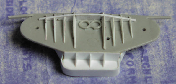
All moulded detail on the top side was removed and the platform filed smooth (apart from the two circular platforms for the 5-inch range-finders at the outer ends). Replacement shielding and life rails are best understood by reference to the photograph. I used styrene strip to represent the splinter mattresses hung from the rails.
Other additions included two work benches and the access hatch in the deck. Support brackets for the underside of the platform were cut from styrene strip.
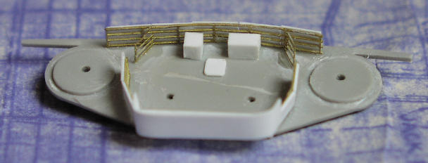
Above: Foretop 5-inch fire control platform.
Construction of the rangefinder tubs and director pedestals are described below under 5-inch fire control.
Stage 11: stack structure
Kit parts: 18
Scratch parts: 65
PE parts: 11
Time: 11.5 hours
The base of the structure (kit parts C1 and C2) is accurate in dimensions and for the position of doors and scuttles. However, both parts are incorrectly joggled outwards near the aft end. On the inboard side this additional width would overlap part of the torpedo elevator in the flight deck. The joggles were easily corrected and C1 and C2 made flush. This was done by cutting, trimming and recementing, making adjustments for length on C1 by reinforcing the inside and inserting styrene strip in the resulting gap. The aft bulkhead (part C18) was reduced in width to fit and the scuttle holes filled.
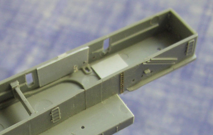
Above: Joggles removed from structure and sides made straight. The rectangle of white styrene sheet on the deck head was to seal a gap left after removing some irrelevant moulded detail on the upper side.
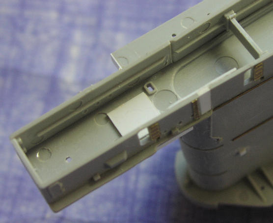
The light AA platform on the outboard side is too high, being flush with the deck level for what was the No.3 8-inch mounting. It should be lower but, given that I planned to use the GMM PE supporting braces between the platform and the deck edge, and would not be able to reduce these in height, decided against altering the height of the platform. It runs too far aft so was cut back to just forward of the moulded-on vertical ladder on the outboard side. This ladder was removed, to be replaced with PE. At the aft end l removed all moulded splinter screen, gun tub and director base structure detail. With the joggles in the structure corrected as described above, the deck above it now exhibited the correct overlap. However, this was not the same width along its entire length and I narrowed it on both sides at the correct positions.
The two very prominent 8-inch ammunition hoists at the rear of the structure (never removed) were fashioned from balsa wood.
Splinter shields for the 1.1-inch mount aft of the stack were made following the same style as those forward of the bridge. Vertical stiffeners were added the length of the outboard gun gallery at 5mm intervals. Six vertical stiffeners in three pairs were added to the 1.1-inch mount splinter shield at the forward end of the stack structure.
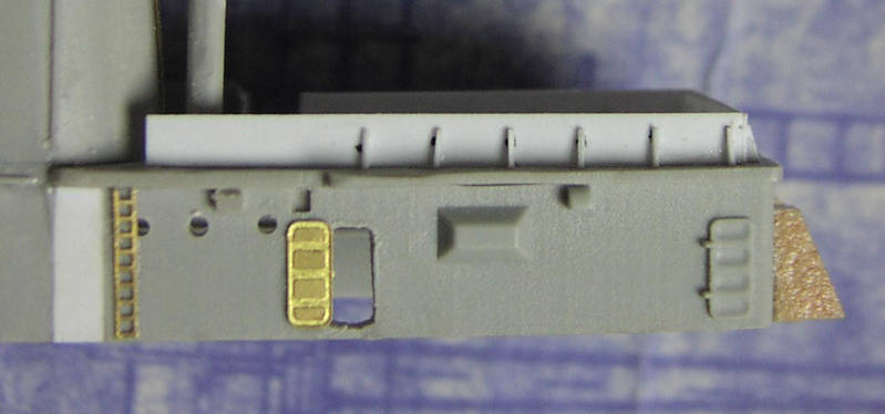
Above: Aft end of stack structure showing scratch-built splinter shielding and 8-inch ammunition hoists on rear face.
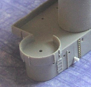
Above: Forward end of stack structure showing vertical stiffeners added to gun tub and port side winch (see next section).
On the inboard side of the stack the moulded-on vertical ladder (not to be replaced) and clutch of nearby vertical vent pipes (the latter a distinguishing feature of Saratoga but not of Lexington) were removed. The horizontal jack rod along the base of kit part C11 is fine, but I removed this and fitted a replacement (made from brass wire, later replaced with stretched sprue) slightly lower down to help mask the join with the lower structure. The upper horizontal jack rod running all round the stack was removed (not to be replaced). All other vertical ladders were removed. Two of the doors on the inboard side were opened out and PE doors fitted in the open position. Three deck floodlights (square styrene strip) were mounted midway up the stack (note that these are not equally spaced), and a jack rod (brass wire, later replaced with stretched sprue) run horizontally on the inboard side corresponding to the moulded-on one on the outboard side.
I drilled and squared-off manholes in the gun gallery corresponding with the position of vertical ladders below and mounted rectangular styrene blocks representing the 0.5-inch ammunition hoist outlets. The vertical cables and 0.5-inch ammunition hoists running up the outboard side of the stack between the lower and upper gun galleries were made from different diameters of brass wire. There was only one vertical ladder running up the side of the stack and this was on the outboard side at the aft end. There was originally a shorter vertical ladder on the outboard side at the fore end leading up to a small intermediate platform that in turn gave ladder access to the secondary con and pri-fly positions on the forward face of the stack. When the latter were replaced by the radar cabin these ladders and the platform were removed. A PE ladder was fixed to the rear of the stack between the lower platform and the deck below.
About the Author


FROM: ENGLAND - EAST ANGLIA, UNITED KINGDOM
1966-1971: Art college in Twickenham and Blackpool 1971-1973: Commercial art studio, Ipswich, Suffolk 1973-1975: Philips, Eindhoven, Netherlands 1975: Lecturer Ravensbourne School of Art, Bromley, Kent 1976: Marketing Communications, IT systems and software house, London. Got married...
Comments

Hi Joseph,
Yeah, it was a lot of research. I was DETERMINED to make it abolutely as accurate as possible. What I don't understand is how Trumpeter got so much of it grotesquely wrong. Anyway, thanks for your comments. I sure hope you find my feature useful - from what I've seen the 1:700 from Trumpeter is just a scaled down version of the 1:350 kit, including everything that's wrong with the big one!
JUL 08, 2008 - 05:36 AM
Hi Rui
Well, well, well. I used to be a graphic designer myself as well. And a copywriter. Hence what I hope is a deal of professionalism in my SBS guide.
The whole project spanned two years. I didn't dare start another model in all that time, knowing it would simply delay completion and possibly I would lose my motivation. Sometimes it was very hard to keep going - the progress when doing the armament and the air group seemed so slow. I really had to force myself to keep going.
Thanks for the advice on using Clearcoat on the decals. Actually, that is what I did use, in order to soften the decals so they would lay close on the curved fuselage sides, to get them to stick, and to try and dull them down. All the planes were matt varnished as well, but that still didn't kill the decal edge reflection.
You can see some of my 1:700 stuff at: LINK If you select my name from the top of the menu on the left you can see all my galleries.
By the way, the 1:700 Trumpeter Lexington looks like just a scaled-down version of the 1:350 version, including everything that is wrong and inaccurate. So please, please, do use all the research I did to get it right. I look forward to seeing the result!
Regards, Chris
JUL 08, 2008 - 05:48 AM
Jim
Your comments an honour indeed. I have followed your work over the years at Modelwarships.com and you really are the best. Counting the hours is actually a way of giving myelf a sanity check! Which is why to some extent the whole project took me two years from start to finish.
Regards, Chris
JUL 08, 2008 - 05:53 AM

Thanks for taking time to answer to my questions!
I have the 1/700 Trumpeter model, for Coral Sea fit, so I guess you have done all the research for me - but still, I have to get the work myself!
Not for now, but for a "near" future (I am currently working on three projects, one a full scratch all in 1/700).
Thanks for the link, and since my memory is better for graphics, than for names, I can say that I had already seen your Sara / Lex duo in MW.
Please keep up - keep your ship models afloat!
Rui
JUL 08, 2008 - 05:57 AM

Are you sure that thing is a model. It looks so real. In some of those photos it looks too real. Nice job. Amazinglly nice job. Great tribute to those who sailed, fought and died on board the original Lady Lex carrier. Nice work.
JUL 11, 2008 - 08:46 AM

Hi Chris,
Sorry no plans on any new 1/350 items.
You could use my YC-728 or 829 for an open ammunition lighter. I have some photos of their use as such.
JUL 15, 2008 - 07:06 AM

Hello Chris:
I just finished reading your build log. Outstanding work and very well written. I have this kit, not sure I want to tackle all the inaccuracies vice just building an OOB kit, but, your work is inspirational and you presented a lot of neat ideas to enhance the kit. I will be referencing your build log when I tackle mine. Thanks for posting and sharing.
FEB 10, 2015 - 08:49 AM

Mark, I doubt Chris will respond as this is a 7 year old tread and Chris last signed in 7 years ago.
FEB 10, 2015 - 09:13 AM

wow, awesome model building.
well worth resurrecting the thread and feature.
FEB 11, 2015 - 09:17 AM
Copyright ©2021 by Chris Smithers. _OPINIONS Model Shipwrights, KitMaker Network, or Silver Star Enterrpises. Images also by copyright holder unless otherwise noted. Opinions expressed are those of the author(s) and not necessarily those of Model Shipwrights. All rights reserved. Originally published on: 2008-07-04 00:00:00. Unique Reads: 23646

WEB HOSTING BY


Copyright ©2021 Model Shipwrights and Kitmaker Network, a subsidiary of Silver Star Enterprises
All Rights Reserved. Please read our Conditions of Use and Privacy Policy.
All Rights Reserved. Please read our Conditions of Use and Privacy Policy.