

Go to modelshipwrights.com for the current dynamic site!


1⁄350USS Lexington (CV2) 1927-1942
23
Comments
Stage 7: lower bridge structure
Kit parts: 8
Scratch parts: 77
PE parts: 19
Time: 10.5 hours
This kit is nothing if not consistent. The issues with the hull translated to this structure. So, its off with the rain water throw-off strips over scuttles, and detailed examination of scuttle and door positions. Not quite as bad as the hull, but a number of minor but nevertheless inexcusable errors if the builders plans had been followed to the letter. On the other hand, the weapons deck forward of the bridge is so grossly inaccurate as to be unusable, and there are a number of significant errors in the structure which will be dealt with below. This stage of the bridge construction goes up as far as the deck of the navigating bridge (part E21).
There is an incorrect angled cut-away on the port forward corner of part E1 and three scuttles in the forward bulkhead (part E18) which should not be there. Both these were corrected by overlaying with thin styrene sheet.
The doors at the aft end of the structure are incorrectly positioned. These were filed off and replaced by photo-etched parts in the correct location.
I chose to open up three of the doorways on the port side and one on the starboard side. To prevent a clear line of sight through these doorways (the interior was compartmented) I fitted a central bulkhead running the length of the interior of the structure up to the height of the superimposed weapons platform.
The recesses for loudspeakers (parts F26) and paravane booms (parts E9, E23 and E26) were filled and sanded smooth.
The superimposed weapons deck (part E35) was discarded and replaced with a scratch-built structure incorporating vertical splinter shields and supporting ribs. There is an angle on the forward starboard side of the deck; the builders plan states: Cut to clear guns at 60 degree after training.
The jointing of the forward face of the bridge structure (part E22) to the sides is quite clumsy and left unsightly gaps that would have needed filling and sanding smooth. I found it easier simply to sheet off the flat faces above and below the curved conning tower face with styrene sheet.
Made up of three parts, the curved conning tower front does not present a smooth transitional curve round to the sides. This was easily solved using thin styrene sheet cemented over the exiting parts. I did not attempt to cut the peep holes in it, since in real life these measured a mere twelve inched wide by two inches high, scaling down to 0.85 x 0.1mm. I decided to render these later using decal material or whatever else suitable came to mind at that stage.
The navigating bridge deck (part E21) is inset on both sides. Certainly this is the way the ship was originally constructed, but amendments to the drawing and photographic evidence indicates that Lexington (but not Saratoga) had this modified to run the full width on the starboard side. The moulded-on splinter shielding was carefully cut away and reinstated after filling the gap in the deck with a rectangle of sheet styrene.
The ladder platform (part E8) was grossly oversize, so was discarded and replaced with a scratch-built item.
The upper ladder platform (part E25) was also oversize in the fore and aft direction and of the wrong shape on the leading edge. This was cut back at the correct angle, usefully removing the moulded ladder location tab at the same time.
On the inboard side there were two support struts between the upper ladder platform (E25) and the underside of the signalling deck above. On the outboard side the lower end of these struts connected directly to the mast struts. These were added later after the bridge structure was fixed to the flight deck. This was to take account of any flexing in the strut during the fixing process. There were also suspension struts between the lower outer corners of the flag lockers and the underside of the signalling deck. All these parts were made from very thin brass wire.
An access opening was made in the navigating bridge deck above platform E25. To allow this, the locating ribs on the underside for the flag lockers (F17) were removed. A ladder between the two was constructed from three pieces of PE two left over F15 side rails (the ladder section having been used in a boat pocket) and a length of vertical ladder. The rails and support stanchions around the deck opening were made up from pieces of PE rail.
The mounting holes for the searchlights in the rear corners of the deck were filled because the signalling lamps in this area were actually mounted rather further forward, before the mainmast struts.
Paravane booms of the correct length were cut from styrene rod to replace kit items E9 and E23 and mounted in the correct positions E23 is too far forward in the kit. E26 was discarded.
The locating tabs on the flag lockers (F17) were removed, the undersides filed horizontal and the bottom opening covered with thin styrene sheet. This was also used to make the canvas covers on the tops.
External electrical cable, grab rails and voice tube runs were made up from stretched sprue.
Anti-splinter mattresses suspended around the forward windshield were represented with rectangles of styrene strip.
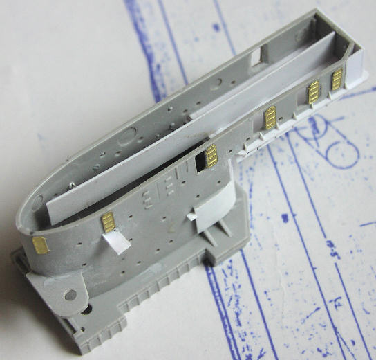
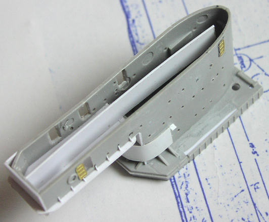
Above and below: Underside view of lower ridge assembly.
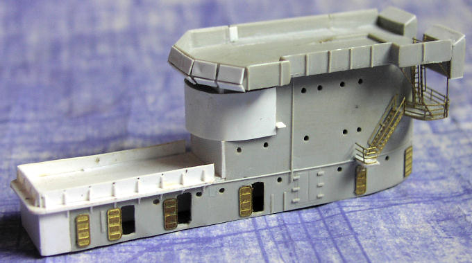
Above: Completed lower bridge structure.
About the Author


FROM: ENGLAND - EAST ANGLIA, UNITED KINGDOM
1966-1971: Art college in Twickenham and Blackpool 1971-1973: Commercial art studio, Ipswich, Suffolk 1973-1975: Philips, Eindhoven, Netherlands 1975: Lecturer Ravensbourne School of Art, Bromley, Kent 1976: Marketing Communications, IT systems and software house, London. Got married...
Comments

Hi Joseph,
Yeah, it was a lot of research. I was DETERMINED to make it abolutely as accurate as possible. What I don't understand is how Trumpeter got so much of it grotesquely wrong. Anyway, thanks for your comments. I sure hope you find my feature useful - from what I've seen the 1:700 from Trumpeter is just a scaled down version of the 1:350 kit, including everything that's wrong with the big one!
JUL 08, 2008 - 05:36 AM
Hi Rui
Well, well, well. I used to be a graphic designer myself as well. And a copywriter. Hence what I hope is a deal of professionalism in my SBS guide.
The whole project spanned two years. I didn't dare start another model in all that time, knowing it would simply delay completion and possibly I would lose my motivation. Sometimes it was very hard to keep going - the progress when doing the armament and the air group seemed so slow. I really had to force myself to keep going.
Thanks for the advice on using Clearcoat on the decals. Actually, that is what I did use, in order to soften the decals so they would lay close on the curved fuselage sides, to get them to stick, and to try and dull them down. All the planes were matt varnished as well, but that still didn't kill the decal edge reflection.
You can see some of my 1:700 stuff at: LINK If you select my name from the top of the menu on the left you can see all my galleries.
By the way, the 1:700 Trumpeter Lexington looks like just a scaled-down version of the 1:350 version, including everything that is wrong and inaccurate. So please, please, do use all the research I did to get it right. I look forward to seeing the result!
Regards, Chris
JUL 08, 2008 - 05:48 AM
Jim
Your comments an honour indeed. I have followed your work over the years at Modelwarships.com and you really are the best. Counting the hours is actually a way of giving myelf a sanity check! Which is why to some extent the whole project took me two years from start to finish.
Regards, Chris
JUL 08, 2008 - 05:53 AM

Thanks for taking time to answer to my questions!
I have the 1/700 Trumpeter model, for Coral Sea fit, so I guess you have done all the research for me - but still, I have to get the work myself!
Not for now, but for a "near" future (I am currently working on three projects, one a full scratch all in 1/700).
Thanks for the link, and since my memory is better for graphics, than for names, I can say that I had already seen your Sara / Lex duo in MW.
Please keep up - keep your ship models afloat!
Rui
JUL 08, 2008 - 05:57 AM

Are you sure that thing is a model. It looks so real. In some of those photos it looks too real. Nice job. Amazinglly nice job. Great tribute to those who sailed, fought and died on board the original Lady Lex carrier. Nice work.
JUL 11, 2008 - 08:46 AM

Hi Chris,
Sorry no plans on any new 1/350 items.
You could use my YC-728 or 829 for an open ammunition lighter. I have some photos of their use as such.
JUL 15, 2008 - 07:06 AM

Hello Chris:
I just finished reading your build log. Outstanding work and very well written. I have this kit, not sure I want to tackle all the inaccuracies vice just building an OOB kit, but, your work is inspirational and you presented a lot of neat ideas to enhance the kit. I will be referencing your build log when I tackle mine. Thanks for posting and sharing.
FEB 10, 2015 - 08:49 AM

Mark, I doubt Chris will respond as this is a 7 year old tread and Chris last signed in 7 years ago.
FEB 10, 2015 - 09:13 AM

wow, awesome model building.
well worth resurrecting the thread and feature.
FEB 11, 2015 - 09:17 AM
Copyright ©2021 by Chris Smithers. _OPINIONS Model Shipwrights, KitMaker Network, or Silver Star Enterrpises. Images also by copyright holder unless otherwise noted. Opinions expressed are those of the author(s) and not necessarily those of Model Shipwrights. All rights reserved. Originally published on: 2008-07-04 00:00:00. Unique Reads: 23646

WEB HOSTING BY


Copyright ©2021 Model Shipwrights and Kitmaker Network, a subsidiary of Silver Star Enterprises
All Rights Reserved. Please read our Conditions of Use and Privacy Policy.
All Rights Reserved. Please read our Conditions of Use and Privacy Policy.