

Go to modelshipwrights.com for the current dynamic site!


1⁄350USS Lexington (CV2) 1927-1942
23
Comments
Stage 3: gallery deck
Kit parts: 12
Scratch parts: 14
PE parts: 10
Time: 4.5 hours
Overall impression: Starboard main bulkhead scuttle and door positions not entirely accurate, but not too bad and easily corrected. However, the port side bulkhead is moulded as a mirror image of the starboard bulkhead and is very inaccurate. Trying to work out what was in the right position and what wasnt was so confusing that I simply filled all the scuttles with filler and then measured out the correct positions. Any that were in the right position were then easily drilled out again. Because I planned to replace all the doors with GMM photo-etched equivalents, the moulded-on doors were simply all removed on both port and starboard sides. As with the hull, all scuttle rain-strips were removed.
The kit provides what resemble light AA range finders for mounting between the two 0.5-inch machine guns in the aft sponsons. The US Navy never employed range finders sited remotely from their associated directors for light AA, and, according to Robert C Stern (The Lexington Class Carriers), the Lexington was never fitted with the light AA directors intended for her before she was lost. Therefore I filled in the mounting holes, not intending to fit these anomalous instruments.
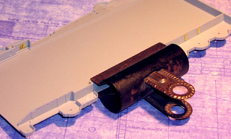
Above: Clamping bulkhead to gallery deck.
The gallery deck moulding - being so large - is quite bendy, so I firmly clamped the side bulkheads to it while the adhesive dried. It might sound obvious, but it is worthy checking that these are absolutely vertical t hey are relatively long and there are no intermediate vertical support ribs.
The complete gallery deck assembly was then cemented in place on the hull. Given the sheer size of it, and the fact that it needs clamping to the hull in a number of different directions, I did this in three stages. First at the forward end, clamping the hull sides to the transverse bulkheads, then at the stern weighted down with 700g of kitchen weights, and finally the mid-section.
There are a large number of circular moulding depressions in the underside of the aft deck and 5-inch sponsons which deserve filling. Given the size of the model and the fact that it is likely to be critically examines at close quarters from different angles, these will definitely show up if they arent filled. Curiously, the starboard light AA sponson beneath the 0.5-inch mounts has a rectangular recess, whereas that on the port side doesnt. This was filled.
I chose to use the Nautilus laser-cut wooden flight deck and this requires the aft round-down to be removed from the moulded kit part along the line that demarcates the joint between flight deck planking and the steel round-down. This was then cemented in place on the aft deck assembly.
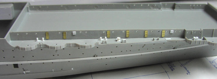
Above: Gallery deck detail, port side.
The incorrect pair of moulded-on mooring bits (bollards) positioned athwartships on each side were removed and replaced by pairs scratch-built from styrene strip and rod. Further pairs were made and installed between the two forward 5-inch mounts on each side. The aftermost mooring rope chocks (fairleads) should be of the closed variety. I removed a little of the tops, bridged the gap with styrene sheet, and filed to shape. Capstans and beds were again made from styrene strip and rod, the latter wasted by filing to give the right profile.
Two ready-use ammunition lockers were mounted on each of the 0.5-inch machine gun platforms. These are pure conjecture, but a reasonable assumption.
Stage 4: forward 5-inch sponsons
Kit parts: 10
Scratch parts: 14
PE parts: 10
Time: 3.75 hours
The hull blister supporting the port sponson has scuttle holes and, since these are not evident on the constructors drawings or photographs, these were all filled. There are moulded-in aligning ribs on the outer edges of the sponsons, designed to help locate the hull blisters below them. I removed these because they are not strictly necessary and might have interfered with getting the blisters to fit snugly against the hull.
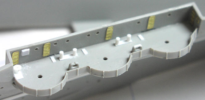
Above: Forward 5-inch sponson detail, starboard side.
It is worth being aware that these sponsons were not mirror images, there being considerable differences in the position of fixtures and fittings. The inboard bulkheads are moulded as mirror images, which is incorrect. Furthermore, three doors are missing from each and some scuttles are missing. This was all corrected. The platforms were fitted to the hull first, followed by the bulkheads. Capstans, mooring bits and chocks were all fashioned as described above for the aft deck, plus three small ammunition hoist scuttles on the deck each side. Photo-etched kapok life rings were mounted on the forward bulkheads. Note that there is also a door in the forward bulkhead on the starboard side only.
Stage 5: forward light AA sponsons
Kit parts: 6
Scratch parts: 4
Time: 1.75 hours
Assembly follows the kit instructions apart from filling in the mounting holes for the discarded light AA range finders (see Stage 3 above). At the forward end of the starboard platform there is a gap between the splinter shield and the hull. This is easily rectified by inserting a small piece of styrene strip. This gap is not so noticeable on the port side and easily cured with a spot of filler. Two ready-use ammunition lockers were mounted on each platform. Again, these are pure conjecture, but a reasonable assumption.
Stage 6: light AA sponsons in boat pocket positions
Kit parts: 3
Scratch parts: 12
Time: 1.75 hours
These are moulded with a deep inboard extension that sits on the former boat pocket deck. Although this makes for strong construction it creates a step-effect at the edges and would also interfere with the various stanchions and ladders already fitted. I removed these inboard extensions and attached the platforms directly to the hull sides but slightly lower down (equivalent to the thickness of the moulded plastic I had removed), creating a flush deck.
The supporting brackets on the underside interfered with some of the scuttle positions, but there was nothing to be done about that since they are on a continuous level the length of the ship. The circular moulding depressions in the undersides were filled before fitting in place. Ready-use ammunition lockers, one per gun, were mounted inboard on the pocket decks. Pure conjecture again, but not unreasonably.
At the painting stage I realised that the coamings were too shallow. This followed a test fitting of a 20mm mount. Although the coamings are slightly under scale-height on the outboard side, the thickness of the plastic deck within gave a scale-height of only about 18-inches, and the 20mm mount looked dreadfully tall and exposed. I remedied this by pulling the platforms off and removing the coamings entirely. I re-cemented them to the hull sides with the intention of replacing the coamings with scale-height styrene strip at a later stage.
About the Author


FROM: ENGLAND - EAST ANGLIA, UNITED KINGDOM
1966-1971: Art college in Twickenham and Blackpool 1971-1973: Commercial art studio, Ipswich, Suffolk 1973-1975: Philips, Eindhoven, Netherlands 1975: Lecturer Ravensbourne School of Art, Bromley, Kent 1976: Marketing Communications, IT systems and software house, London. Got married...
Comments

Hi Joseph,
Yeah, it was a lot of research. I was DETERMINED to make it abolutely as accurate as possible. What I don't understand is how Trumpeter got so much of it grotesquely wrong. Anyway, thanks for your comments. I sure hope you find my feature useful - from what I've seen the 1:700 from Trumpeter is just a scaled down version of the 1:350 kit, including everything that's wrong with the big one!
JUL 08, 2008 - 05:36 AM
Hi Rui
Well, well, well. I used to be a graphic designer myself as well. And a copywriter. Hence what I hope is a deal of professionalism in my SBS guide.
The whole project spanned two years. I didn't dare start another model in all that time, knowing it would simply delay completion and possibly I would lose my motivation. Sometimes it was very hard to keep going - the progress when doing the armament and the air group seemed so slow. I really had to force myself to keep going.
Thanks for the advice on using Clearcoat on the decals. Actually, that is what I did use, in order to soften the decals so they would lay close on the curved fuselage sides, to get them to stick, and to try and dull them down. All the planes were matt varnished as well, but that still didn't kill the decal edge reflection.
You can see some of my 1:700 stuff at: LINK If you select my name from the top of the menu on the left you can see all my galleries.
By the way, the 1:700 Trumpeter Lexington looks like just a scaled-down version of the 1:350 version, including everything that is wrong and inaccurate. So please, please, do use all the research I did to get it right. I look forward to seeing the result!
Regards, Chris
JUL 08, 2008 - 05:48 AM
Jim
Your comments an honour indeed. I have followed your work over the years at Modelwarships.com and you really are the best. Counting the hours is actually a way of giving myelf a sanity check! Which is why to some extent the whole project took me two years from start to finish.
Regards, Chris
JUL 08, 2008 - 05:53 AM

Thanks for taking time to answer to my questions!
I have the 1/700 Trumpeter model, for Coral Sea fit, so I guess you have done all the research for me - but still, I have to get the work myself!
Not for now, but for a "near" future (I am currently working on three projects, one a full scratch all in 1/700).
Thanks for the link, and since my memory is better for graphics, than for names, I can say that I had already seen your Sara / Lex duo in MW.
Please keep up - keep your ship models afloat!
Rui
JUL 08, 2008 - 05:57 AM

Are you sure that thing is a model. It looks so real. In some of those photos it looks too real. Nice job. Amazinglly nice job. Great tribute to those who sailed, fought and died on board the original Lady Lex carrier. Nice work.
JUL 11, 2008 - 08:46 AM

Hi Chris,
Sorry no plans on any new 1/350 items.
You could use my YC-728 or 829 for an open ammunition lighter. I have some photos of their use as such.
JUL 15, 2008 - 07:06 AM

Hello Chris:
I just finished reading your build log. Outstanding work and very well written. I have this kit, not sure I want to tackle all the inaccuracies vice just building an OOB kit, but, your work is inspirational and you presented a lot of neat ideas to enhance the kit. I will be referencing your build log when I tackle mine. Thanks for posting and sharing.
FEB 10, 2015 - 08:49 AM

Mark, I doubt Chris will respond as this is a 7 year old tread and Chris last signed in 7 years ago.
FEB 10, 2015 - 09:13 AM

wow, awesome model building.
well worth resurrecting the thread and feature.
FEB 11, 2015 - 09:17 AM
Copyright ©2021 by Chris Smithers. _OPINIONS Model Shipwrights, KitMaker Network, or Silver Star Enterrpises. Images also by copyright holder unless otherwise noted. Opinions expressed are those of the author(s) and not necessarily those of Model Shipwrights. All rights reserved. Originally published on: 2008-07-04 00:00:00. Unique Reads: 23646

WEB HOSTING BY


Copyright ©2021 Model Shipwrights and Kitmaker Network, a subsidiary of Silver Star Enterprises
All Rights Reserved. Please read our Conditions of Use and Privacy Policy.
All Rights Reserved. Please read our Conditions of Use and Privacy Policy.