Building Bronco's Big Type XXIII Sub
New York, United States
Joined: January 21, 2008
KitMaker: 2,531 posts
Model Shipwrights: 1,244 posts
Posted: Thursday, June 13, 2013 - 09:26 AM UTC
Hello Al,
what about the hatch cover? Sure, that there is no problem in the opened position because of the added lockers? [Quoted text]
No problem with the clearances. Since I had the hatch in hand I decided to add some detail. Replaced the undersized spring with soft wire wrapped around a piece of plastic rod.

The hatch temporarily pinned into place.

Couldn't find a clear picture of the locking mechanism so I sort of winged it. I know, I can almost hear it now, "Blasphemy! Winged it you say, Bah, Humbug!".


Al
New York, United States
Joined: January 21, 2008
KitMaker: 2,531 posts
Model Shipwrights: 1,244 posts
Posted: Friday, June 14, 2013 - 09:06 AM UTC
While I value the improvement PE parts can make over conventional plastic parts, I'm still more than a little leery of, and intimidated by, working with them. so, I wasn't looking forward to jousting with the PE NAXOS radar warning antenna mounted atop the Snorkel. To shape it Bronco does provide you with a plastic piece (Part# E9) to wrap the PE antenna (Part# P1) around. After first annealing the PE part I found it was a little too long when wrapped around the form and needed to be trimmed a hair. I very carefully applied super glue sparingly to the joint and luckily avoided cementing the antenna to the plastic form. After removing it from the form I applied another tiny drop of super glue to complete the joint. After it cured I slid the antenna back onto the form to help align the PE crosspiece (Part# P5). After removing the antenna once more from the form I added the two uprights made from pieces of brass rod. The hardest part turned out to be mounting the antenna to its post atop the Snorkel. To my surprise I had a complete antenna with a lot less blood, sweat, and tears (cussing) than I thought possible.

Despite this modest success, I'm still not about to venture into the realm of 1/350th scale, and I'm thoroughly convinced that those who build those 1/700th scale masterpieces make blood sacrifices by the light of the full moon.
Al

#306
Victoria, Australia
Joined: June 27, 2010
KitMaker: 3,959 posts
Model Shipwrights: 2,777 posts
Posted: Friday, June 14, 2013 - 11:33 PM UTC
Hi Al and Michael!

I've been watching these two magnificent builds from a distance for a while now.
Can I say that both are superb? Your level of scratch building to enhance the standard kit and attention to detail is top notch! Looking forward to seeing more!

Stay home and build models!
In 1/72
Gloster Gladiator MkII for the Bi-planes Campaign
In 1/350
Airfix 1:350 Type 45 Destroyer
England - East Anglia, United Kingdom
Joined: August 12, 2005
KitMaker: 14,499 posts
Model Shipwrights: 1,919 posts
Posted: Saturday, June 15, 2013 - 03:11 AM UTC
Hi Al,
Nice working, looking good.
Alan

'Action this Day'
Winston Spencer Churchill
Nordrhein-Westfalen, Germany
Joined: January 11, 2009
KitMaker: 673 posts
Model Shipwrights: 386 posts
Posted: Saturday, June 15, 2013 - 10:06 AM UTC
There's a drawing in the Rössler book showing the final layout ot the conning-tower and some more holes on the roof. As this detail isn't visible on any pic of U2336 I decided to add them to the model. At first a little positioning device was drilled and this is the result:


I wasn't really satisfied with the upper edge of the tower, because several pics are showing a bulged rim. So I ordered some Evergreen semi-circular profille (1 + 1.5mm); chosen was the smaller one:

...and here's the result with all previous improvements:


...more coherent to the original I think

Michael
Queensland, Australia
Joined: May 20, 2010
KitMaker: 1,230 posts
Model Shipwrights: 1,212 posts
Posted: Saturday, June 15, 2013 - 09:02 PM UTC
Beautiful work once again.....Cheers mark
If I was your Wife I would Poison your Tea
If I was your Husband, I would drink it.
New York, United States
Joined: January 21, 2008
KitMaker: 2,531 posts
Model Shipwrights: 1,244 posts
Posted: Sunday, June 16, 2013 - 02:37 AM UTC
WARNING! WARNING! Part # A17 is the stowage compartment for the life raft. It gets installed in Step 11, but the diagram can be misleading. It looks as if the raised lip on A17 goes on the outside of the tower half, IT DOESN'T! The lip should be on the inside of the tower. I found this out after I had cemented A17 into place. Here is a picture of the lip as I installed it.

I discovered my mistake when test fitting the hatch (Part# B3) to the compartment. The hatch hinges (Parts# B19) wouldn't have fit properly. To correct my error I had to saw the lip off.

This allowed the hatch and its hinges to sit properly. I had decided that it would be easier to glue the hinges (B19) to the hatch rather than trying to cement them to the tower.
Al
England - South East, United Kingdom
Joined: March 01, 2010
KitMaker: 7,078 posts
Model Shipwrights: 6,649 posts
Posted: Sunday, June 16, 2013 - 06:21 AM UTC
Great work Al & Michael.
Real Masterclass in how to turn this beast into something special.
Thanks guys.
Si
#084
Quebec, Canada
Joined: September 14, 2005
KitMaker: 2,485 posts
Model Shipwrights: 1,157 posts
Posted: Sunday, June 16, 2013 - 06:30 AM UTC
Al,
Super job on the tower hatch detail!
I am totally surprised that Bronco overlooked this detail
in this large a scale.
Now I am being tempted to get one.
Perfect opportunity to do some KM figures in 1:35 for
the tower and deck.
Again, great work.
Cheers,
Joe
Västra Götaland, Sweden
Joined: June 16, 2013
KitMaker: 2 posts
Model Shipwrights: 2 posts
Posted: Sunday, June 16, 2013 - 07:19 AM UTC
Thank you! both for providing enough info, inspiration and links to get me gooing on this project. I bought the kit when it was released but haven't been able to find enough info (books are all out of stock it seems) I've finally started gluing stuff now!
// Claes
New York, United States
Joined: January 21, 2008
KitMaker: 2,531 posts
Model Shipwrights: 1,244 posts
Posted: Sunday, June 16, 2013 - 12:08 PM UTC
Quoted Text
Thank you! both for providing enough info, inspiration and links to get me gooing on this project. I bought the kit when it was released but haven't been able to find enough info (books are all out of stock it seems) I've finally started gluing stuff now!
// Claes
Hello Claes, I found a website called BookReader (bookre.org) that has the book "Vom Original Zum Modell, UBoottyp XXIII" by Fritz Kahl that can be seen page for page online at no charge. The text is in German, but there are drawings, plans, and photos.
Al
Västra Götaland, Sweden
Joined: June 16, 2013
KitMaker: 2 posts
Model Shipwrights: 2 posts
Posted: Monday, June 17, 2013 - 08:47 AM UTC
Quoted Text
Hello Claes, I found a website called BookReader (bookre.org) that has the book "Vom Original Zum Modell, UBoottyp XXIII" by Fritz Kahl that can be seen page for page online at no charge. The text is in German, but there are drawings, plans, and photos. Al
Hi Al, yes i saw your link in the earlier post and downloaded it yesterday, sadly though the image quality was very poor and the line drawing was all but hopeless to interpret for me (atleast with any detail) i still have hope on getting my hands on the book "live" but the previous work in this thread and the e-book in the link is a very good starting point.
what i realized most of all is that none of the uboats seems to have been the same, so it opens up for a alot of "well it looks good so..." solutions.
So far i have only glued the torpedo tubes and epoxied in nuts for a brass stand.
// Claes
South Carolina, United States
Joined: June 17, 2013
KitMaker: 78 posts
Model Shipwrights: 78 posts
Posted: Monday, June 17, 2013 - 10:42 AM UTC
Hello to all; newbie here. Just registered. I have the kit and the book already, but I'm holding off to see what kicks out for PE or details for this big model. One thing intrigues me: the brow platform on the upper deck. Big square block; looks like it's more than just a platform to me. Any thoughts on the cleating inside it, guys?
I will super-detail the snorkel when I build; you've all been an inspiration to me. Nicely done, gentlemen!
New York, United States
Joined: January 21, 2008
KitMaker: 2,531 posts
Model Shipwrights: 1,244 posts
Posted: Wednesday, June 19, 2013 - 06:19 AM UTC
Getting ready to close up the hull halves. Installed the torpedo tubes and added some tubing for the brass rod I'll use to mount the sub on its base.


Bronco includes a partial deck inside the hull hence the shorter tube up forward, I added a thin sheet of plastic to hide the seam in that deck that would have been visible if anyone bothered to shine a flashlight down through the hatches.

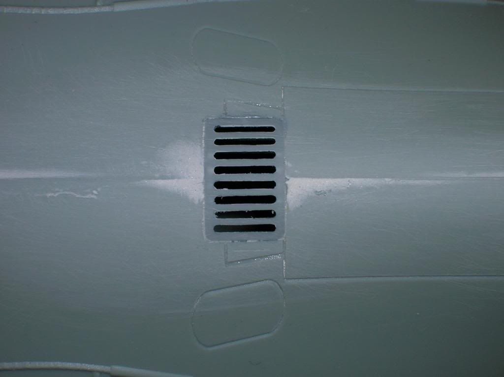
I stole a page from Michael's playbook and added the grate to the upper rear hull. This was sourced from a MiniArt Street Accessories set.

Guess I'll have to build a diorama sometime just to use the rest of the set.
Also found time to add the hook-like upper bracket for the life-preserver.

That's all for now.
Al
England - East Anglia, United Kingdom
Joined: August 12, 2005
KitMaker: 14,499 posts
Model Shipwrights: 1,919 posts
Posted: Wednesday, June 19, 2013 - 06:43 AM UTC
Terrific work Al, always inspirational.
Alan

'Action this Day'
Winston Spencer Churchill
New York, United States
Joined: January 21, 2008
KitMaker: 2,531 posts
Model Shipwrights: 1,244 posts
Posted: Wednesday, June 19, 2013 - 08:11 AM UTC
Thanks Alan, but it's more like perspiration than inspiration me thinks.
Al
South Carolina, United States
Joined: June 17, 2013
KitMaker: 78 posts
Model Shipwrights: 78 posts
Posted: Wednesday, June 19, 2013 - 01:27 PM UTC
Okay ... got another question. The exhaust duct discharging overboard on the port side appears to be a secondary silencing device in combination with the muffler for, perhaps, patroling close to shore. So I see actually three exhaust ports: that overboard duct, the vertical exhaust vent inside the sail, and the aft exhaust pipe on the snorkle mast assembly. It appears that the output of the muffler could be directed to three places ... any thoughts on this?
New York, United States
Joined: January 21, 2008
KitMaker: 2,531 posts
Model Shipwrights: 1,244 posts
Posted: Thursday, June 20, 2013 - 12:01 AM UTC
I believe you're quite correct. There are three exhaust ports, two for surface running, and the one in the Schnorkel for running the diesel while submerged. The side exhaust, by venting underwater , does act like a 'silencer'. American PT boats used a similar set up for their exhausts.
Al
Nordrhein-Westfalen, Germany
Joined: January 11, 2009
KitMaker: 673 posts
Model Shipwrights: 386 posts
Posted: Thursday, June 20, 2013 - 04:14 AM UTC
...sorry gents, but you're not right!. There are only 2 ways for the exhaust:
one aside the muffler venting under water, when the boat is on surface. And the other is the tube under the snorkel (facing bachwards), when the boat is diving.
The 2 tubes inside the sail were for outgoing air from the boat and ingoing air for the diesel engine. A 3rd way for venting the boat was running the diesel, sucking the air through the opened hatch (not the best choice while diving...
)
..and here the diagramm showing air and exhaust flow (from "U-Boottyp XXIII" by Rössler):

Michael
New York, United States
Joined: January 21, 2008
KitMaker: 2,531 posts
Model Shipwrights: 1,244 posts
Posted: Thursday, June 20, 2013 - 05:47 AM UTC
Hello Michael, I was looking at Plan# 5 on page 79 of Kahl's book and I could be wrong, but it seemed to me that there was a connection between the muffler and the after-most vertical pipe inside the tower. I know that U.S. PT boats vented their exhaust underwater to help muffle engine noise but it was limited to idling an engine or running at slow speeds. Check out that plan and let me know what you think, OK?
Al
South Carolina, United States
Joined: June 17, 2013
KitMaker: 78 posts
Model Shipwrights: 78 posts
Posted: Thursday, June 20, 2013 - 05:49 AM UTC
Now that makes much better sense ... the fwd sail pipe is main induction and the aft sail pipe is exhaust air ... so there was a ventilation fan somewhere in there making that combo work. We used to use diesel exhaust to blow down the main ballast tanks (they all leak by a little through the vents) and save the air banks ... and the diesel oil coating helped the insides of the MBTs, too ... but I don't see that option on this boat. I appreciate the response, mates.
New York, United States
Joined: January 21, 2008
KitMaker: 2,531 posts
Model Shipwrights: 1,244 posts
Posted: Thursday, June 20, 2013 - 07:04 AM UTC
Look Ma, No tape!

The hull halves are joined together. The seams did require a little putty.

There were no gaps just a slight step in some places. The keel was the area requiring the most attention. A large section of the seam on the upper hull will be hidden by the wooden deck grates (if used). Here's the 'sewer' grate blended in.
The business end.

Part # A18 cemented in place.

Don't know what it is or what its function might be. Maybe Michael can shed some light on that. I do miss the old days when instructions labeled a part as well as numbered it.
Al
Nordrhein-Westfalen, Germany
Joined: January 11, 2009
KitMaker: 673 posts
Model Shipwrights: 386 posts
Posted: Thursday, June 20, 2013 - 07:56 AM UTC
...I'm not really sure, but it seemed to me too, that there's a connection between the muffler and the after-most vertical pipe inside the tower. And just that was my way to scratch that tubes. On plan #5/page 79 the pipe is titled "D(iesel)abluftmast"
with a connection to the muffler. But on that last diagramm it's only titled "Abluftmast"
without the connection and the "D" for "Diesel" and so is the german description in my 2. book. Let's leave it at that - all plans are post-war drawings; who knows really what's right? I for myself will not alter the tubes for nearly nothing will be visible afterwards...
Part A18? A riddle!
Michael
South Carolina, United States
Joined: June 17, 2013
KitMaker: 78 posts
Model Shipwrights: 78 posts
Posted: Thursday, June 20, 2013 - 08:52 AM UTC
Earlier mention was made of the middle thin rod running between the two snorkle tubes and I think I know what that is. I believe that when the snorkel is cranked down all the way, the bottom end of that rod contacts a pad and causes it to move upward against the snorkle ball float linkage to force the ball up tighter against the stops ... at its top limit. This effectively tightens the seal on the balanced spool valve inside the snorkle air chamber ... to keep water from entering the air tube at deep depths. I think they wanted more pressure on the seals than the ball's positive buoyancy was providing.
As nearly none of the photos shows that rod, I think it was probably a late modification ... and maybe a temporary gig at that. Just my take on that ...
New York, United States
Joined: January 21, 2008
KitMaker: 2,531 posts
Model Shipwrights: 1,244 posts
Posted: Thursday, June 20, 2013 - 09:08 AM UTC
Quoted Text
...I'm not really sure, but it seemed to me too, that there's a connection between the muffler and the after-most vertical pipe inside the tower. And just that was my way to scratch that tubes. On plan #5/page 79 the pipe is titled "D(iesel)abluftmast" with a connection to the muffler. But on that last diagramm it's only titled "Abluftmast" without the connection and the "D" for "Diesel" and so is the german description in my 2. book. Let's leave it at that - all plans are post-war drawings; who knows really what's right? I for myself will not alter the tubes for nearly nothing will be visible afterwards...
Part A18? A riddle!
Michael
Thanks for the prompt reply. Whether or not the exhaust connects doesn't really matter as far as the model is concerned, as you say it won't show anyway. It was just curiosity on my part.
Al