After completing the pilothouse interior I turned my attention to the bridge roof and upper air defense station.
Nichimo’s rendition is accurate, but it is also rather heavy. Since this is a high visibility area, I made the extra effort to replace the kit detail with finer structures built up from sheet plastic.
The sides were built up to match the bridge wing sides. The complex-looking construction at the front was a directional wind baffle; it deflected wind from the forward motion of the ship upward to allow the lookouts in the open air station to work unimpeded by wind blast.
You are viewing the archived version of the site.
Go to modelshipwrights.com for the current dynamic site!
Hosted by Jim Starkweather
1/200 Nichimo Hatsuzuki build
TimReynaga
Associate Editor
California, United States
Joined: May 03, 2006
KitMaker: 2,500 posts
Model Shipwrights: 1,830 posts
Joined: May 03, 2006
KitMaker: 2,500 posts
Model Shipwrights: 1,830 posts
Posted: Saturday, June 27, 2020 - 07:33 AM UTC
Posted: Saturday, June 27, 2020 - 08:45 AM UTC
Tim,
Great looking modifications to the outlook bridge. You have a very nice skill at scratch building.
Mark
Great looking modifications to the outlook bridge. You have a very nice skill at scratch building.
Mark
SpeedyJ
Bangkok, Thailand / ไทย
Joined: September 17, 2013
KitMaker: 1,617 posts
Model Shipwrights: 44 posts
Joined: September 17, 2013
KitMaker: 1,617 posts
Model Shipwrights: 44 posts
Posted: Saturday, June 27, 2020 - 12:40 PM UTC
Tim I'm not a shipyard guy, but I really like this build. Watched this from the side line as a 'lurker'. Will follow with admiration, as from now on.
Posted: Monday, June 29, 2020 - 12:11 AM UTC
Tim, your modifications to the bridge are really "on point"
rdt1953
New Jersey, United States
Joined: February 06, 2015
KitMaker: 1,098 posts
Model Shipwrights: 34 posts
Joined: February 06, 2015
KitMaker: 1,098 posts
Model Shipwrights: 34 posts
Posted: Monday, June 29, 2020 - 06:29 AM UTC
Hi Tim - Really admire what you are doing with this . I seem to recall a photo or two that indicated that at least some of the bridge windows on some Japanese destroyers opened by dropping the sash- that would be a neat detail to include if this class had that feature as it would allow more of your nice work to be seen . Also, was this class around pre war ? I like the name in large Kanji characters on the hull sides.
( Don’t you love it when bystanders tell you how to do your job ? ha- ha )
Keep at it ! Richard
( Don’t you love it when bystanders tell you how to do your job ? ha- ha )
Keep at it ! Richard
bwiber
Washington, United States
Joined: August 03, 2008
KitMaker: 436 posts
Model Shipwrights: 31 posts
Joined: August 03, 2008
KitMaker: 436 posts
Model Shipwrights: 31 posts
Posted: Monday, June 29, 2020 - 07:45 AM UTC
Quoted Text
The sides were built up to match the bridge wing sides. The complex-looking construction at the front was a directional wind baffle; it deflected wind from the forward motion of the ship upward to allow the lookouts in the open air station to work unimpeded by wind blast.
As a tanknut, I really appreciate your explanations about how things work. Unless you had mentioned the air deflection I would have just thought it was some overdone design. Thank you for the explanation(s)....
Bob
TimReynaga
Associate Editor
California, United States
Joined: May 03, 2006
KitMaker: 2,500 posts
Model Shipwrights: 1,830 posts
Joined: May 03, 2006
KitMaker: 2,500 posts
Model Shipwrights: 1,830 posts
Posted: Monday, June 29, 2020 - 08:40 AM UTC
Mark, Robert, and Russ, thanks. I’m not really much of a scratchbuilder, but working in this relatively large scale sure helps make things easier!
Thanks Richard, and good idea – it would be nice to leave all the windows open and so not have to deal with the transparencies, plus of course the better visibility of the interior details. I think I’ll do that!
I like the large Japanese characters often seen painted on destroyer hulls too, but unfortunately Hatsuzuki never had them. The only known photo of her was from her December 1942 sea trials, and her hull sides were plain gray. I may add the Hiragana characters for the ship's name to the stern, though.
Don’t worry about that – I welcome good ideas whatever the source!
My pleasure Bob. Sometimes I wonder whether I’m going on about things too much, so it’s good to hear that my comments are useful!
Quoted Text
Hi Tim - Really admire what you are doing with this . I seem to recall a photo or two that indicated that at least some of the bridge windows on some Japanese destroyers opened by dropping the sash- that would be a neat detail to include if this class had that feature as it would allow more of your nice work to be seen .
Thanks Richard, and good idea – it would be nice to leave all the windows open and so not have to deal with the transparencies, plus of course the better visibility of the interior details. I think I’ll do that!
Quoted Text
...Also, was this class around pre war ? I like the name in large Kanji characters on the hull sides.
I like the large Japanese characters often seen painted on destroyer hulls too, but unfortunately Hatsuzuki never had them. The only known photo of her was from her December 1942 sea trials, and her hull sides were plain gray. I may add the Hiragana characters for the ship's name to the stern, though.
Quoted Text
(Don’t you love it when bystanders tell you how to do your job? ha- ha ) Keep at it ! Richard
Don’t worry about that – I welcome good ideas whatever the source!
Quoted Text
As a tanknut, I really appreciate your explanations about how things work. Unless you had mentioned the air deflection I would have just thought it was some overdone design. Thank you for the explanation(s)....
Bob
My pleasure Bob. Sometimes I wonder whether I’m going on about things too much, so it’s good to hear that my comments are useful!
Posted: Monday, June 29, 2020 - 09:00 AM UTC
Holy smokes, Tim! That detail you've built is awesome!
Gaxz
Gaxz
TimReynaga
Associate Editor
California, United States
Joined: May 03, 2006
KitMaker: 2,500 posts
Model Shipwrights: 1,830 posts
Joined: May 03, 2006
KitMaker: 2,500 posts
Model Shipwrights: 1,830 posts
Posted: Friday, July 03, 2020 - 05:38 PM UTC
Thanks Gary.
After drilling out the mounting holes for the etched brass handgrabs with a tiny No. 80 bit (56 holes for 28 handgrabs on the front and sides!), I set about drilling out and fitting the 19 brass mounts for the footrails.
The footrails themselves are 34 gauge brass wire strung through the tiny etched brass eyelets from the Gold Medal Models set.
Navigation light assemblies and wiring entry points to the structure had been molded on by Nichimo just forward of the bridge wings, but they were a little flat. I scraped them away and built up new ones from plastic sheet and rod.
RedDuster
England - South East, United Kingdom
Joined: March 01, 2010
KitMaker: 7,078 posts
Model Shipwrights: 6,649 posts
Joined: March 01, 2010
KitMaker: 7,078 posts
Model Shipwrights: 6,649 posts
Posted: Friday, July 03, 2020 - 09:05 PM UTC
Very neat work Tim, the wind deflectors look excellent.
drilling out all the steps and hand holds can get a bit tedious in this scale, but the results are well worth it.
Very much enjoying following this build.
Cheers
Si
drilling out all the steps and hand holds can get a bit tedious in this scale, but the results are well worth it.
Very much enjoying following this build.
Cheers
Si
Posted: Friday, July 03, 2020 - 09:14 PM UTC
Totally agree with what Si said, Tim
The level of detail you're incorporating is fantastic!
Posted: Saturday, July 04, 2020 - 04:31 AM UTC
Quoted Text
Very neat work Tim, the wind deflectors look excellent.
drilling out all the steps and hand holds can get a bit tedious in this scale, but the results are well worth it.
Very much enjoying following this build.
Cheers
Si
Ditto!
Mark
TimReynaga
Associate Editor
California, United States
Joined: May 03, 2006
KitMaker: 2,500 posts
Model Shipwrights: 1,830 posts
Joined: May 03, 2006
KitMaker: 2,500 posts
Model Shipwrights: 1,830 posts
Posted: Saturday, July 04, 2020 - 12:18 PM UTC
Thanks guys!
Having attached the GMM brackets and wire footrails, I dry fitted the handgrabs as well to get a sense of how the finished structure will look. Then I started wondering if the 1/200 footrails, and especially the support brackets, might be a little heavy...
so I temporarily attached a small section of alternative footrail just above it cut from 1/400 scale safety railing as a comparison.
The 1/200 fittings are nice, but this photo of the Yugumo-class destroyer Makinami in 1943 shows the footrails to have been fairly fine – more like the 1/400 test piece.
Looks like I’ll be making some changes again...
Posted: Saturday, July 04, 2020 - 04:33 PM UTC
Love the work, Tim.
One of the most frustrating things about scale warship building is finding materials that are fine enough to be in scale.
I once bought some modelkasten line. I can't remember the diameter of the stuff... but I couldn't even feel it between my fingertips unless it was moving. And it was nearly impossible to see. So fine, that I didn't even use any for models.
Posted: Sunday, July 05, 2020 - 06:25 AM UTC
Tim,
Standing further back would make the wire thinner....LOL. Are you sure it as thin as you think it is? You are not mistaking the shadow as the rigging. I been looking at that photo and it looks heavy to me.
Mark
Standing further back would make the wire thinner....LOL. Are you sure it as thin as you think it is? You are not mistaking the shadow as the rigging. I been looking at that photo and it looks heavy to me.
Mark
TimReynaga
Associate Editor
California, United States
Joined: May 03, 2006
KitMaker: 2,500 posts
Model Shipwrights: 1,830 posts
Joined: May 03, 2006
KitMaker: 2,500 posts
Model Shipwrights: 1,830 posts
Posted: Sunday, July 05, 2020 - 11:03 AM UTC
Quoted Text
Tim,
Standing further back would make the wire thinner....LOL. Are you sure it as thin as you think it is? You are not mistaking the shadow as the rigging. I been looking at that photo and it looks heavy to me.
Mark
Hi Mark,
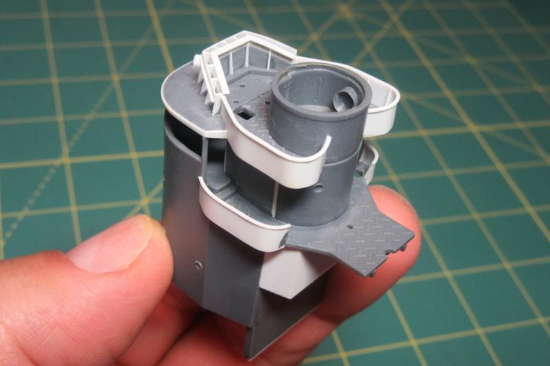
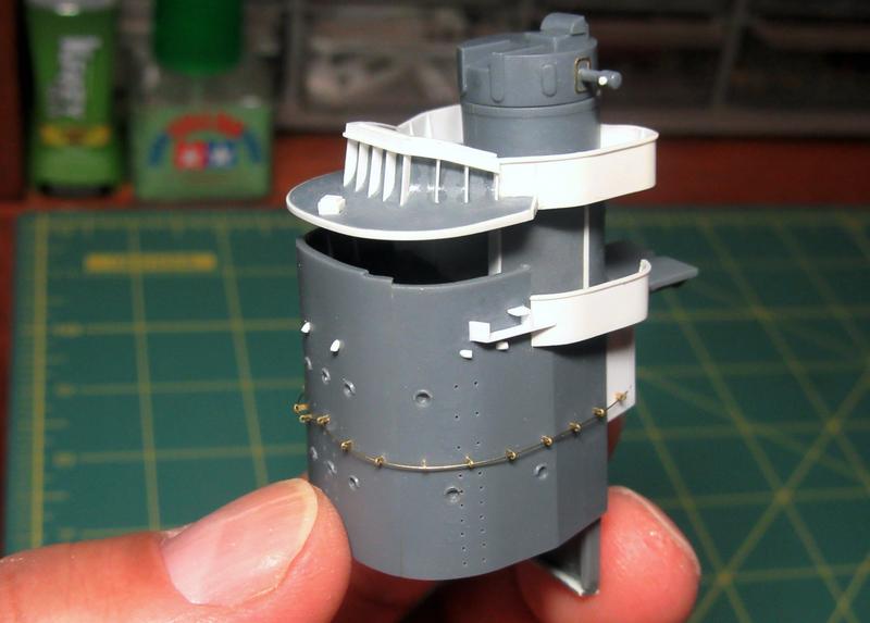
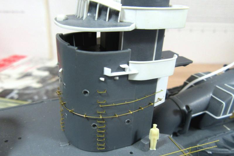
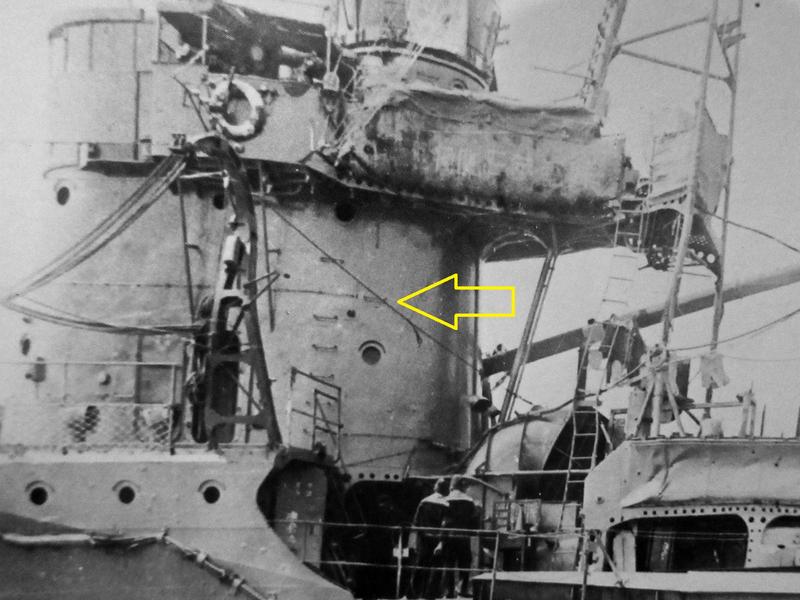
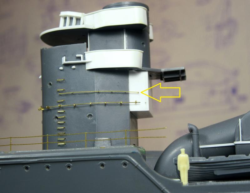
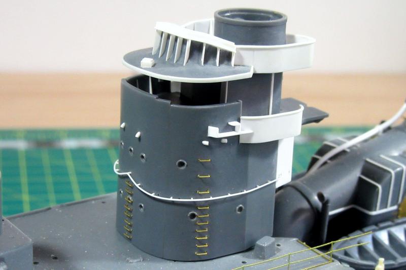
It is the etch brass mounts I used for the footrails that seem to me to be heavier than they should be. Take a look at the footrails along the funnels of the destroyer Samidare:
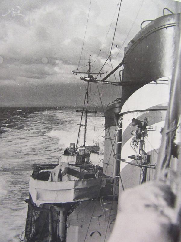
The real footrails look very fine to my eyes, with the mounts for them being the same diameter. The 34 gauge wire I had used looks right, but the etched brass mounts are heavier. The fault is mine. Gold Medal Models actually identifies their brass mounts as "handrail supports" - the footrails and their supports were of a different design.
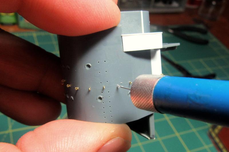
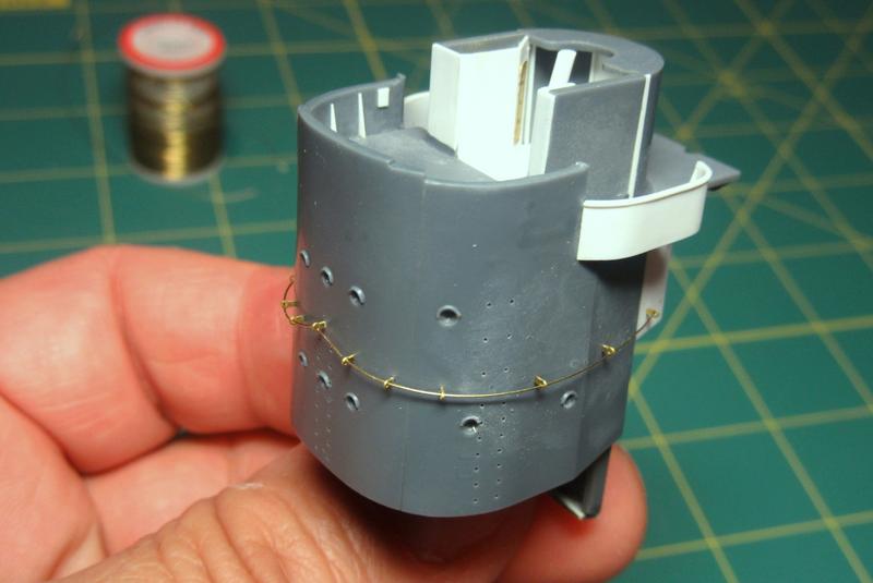
Before tearing out the offending footrail mounts I did some tests to make sure there was a better alternative.
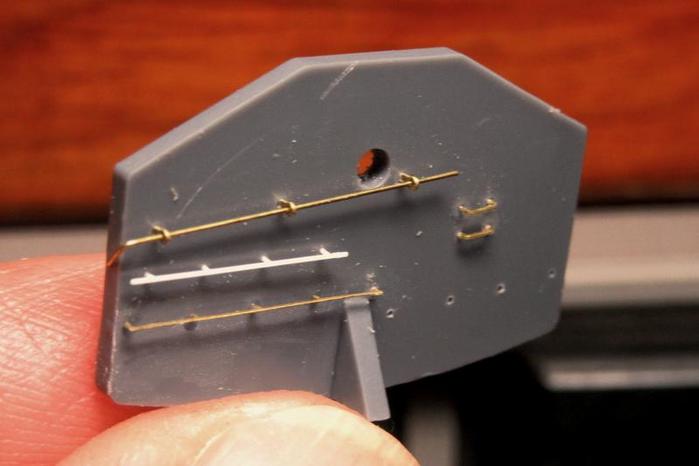
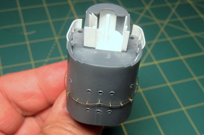
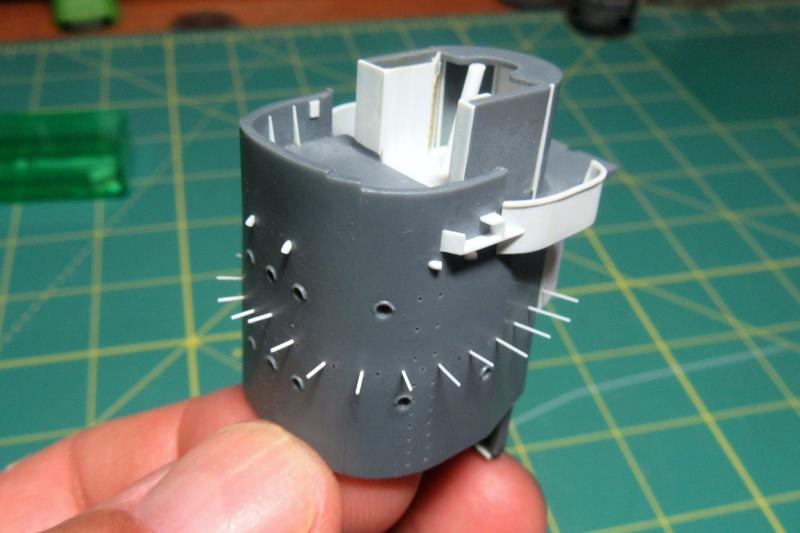
Taking a scrap piece, I mounted the GMM fittings with 34 gauge wire as I had on the bridge structure. At the bottom I attached the piece cut from 1/400 scale etched brass railing, and the middle section was made from .010 inch plastic rod.
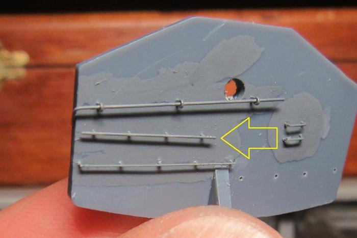
I painted the samples to get a better idea of how each would ultimately look.
The top piece looked the best for detail, but the mounts remained oversized. The etched brass rail piece at bottom was definitely the finest, but at this large scale it was evident that the flat etch lacked the round outline of the original footrails. The middle piece made from plastic rod turned out to be the best; it is a nice combination of the two, being convincingly three-dimensional yet fine enough to appear correctly scaled.
Posted: Sunday, July 05, 2020 - 02:05 PM UTC
Tim,
My mistake, I thought you where referring to the rail and not the mounting. I agree the middle example does match up nicely with the photo.
Mark
My mistake, I thought you where referring to the rail and not the mounting. I agree the middle example does match up nicely with the photo.
Mark
TimReynaga
Associate Editor
California, United States
Joined: May 03, 2006
KitMaker: 2,500 posts
Model Shipwrights: 1,830 posts
Joined: May 03, 2006
KitMaker: 2,500 posts
Model Shipwrights: 1,830 posts
Posted: Saturday, July 11, 2020 - 08:40 AM UTC
Having committed to redoing the footrails, I removed the etched brass supports and filled in the 13 holes.
The finer plastic supports will be closer together than the larger brass ones had been, so 21 new holes were drilled out with a #80 bit. A section of 1/400 brass railing served as a template to establish the spacing.
The .010 inch plastic rod supports went into the new holes. I left them long to make it easier to correct their orientation as the cement dried.
To trim them down to size, I made a simple tool from a piece of .015 inch plastic sheet with a .018 inch hole made with the smallest punch from the Waldon Model products Sub-Miniature punch & die set.
Placing the hole over the supports, I cut each rod down to establish a uniform .015 inch length.
Then the rail was attached with small application of Tamiya Extra Thin Cement.
With the new footrails in place, I secured the 28 brass handgrabs.
Posted: Saturday, July 11, 2020 - 01:04 PM UTC
It's hard to find a better word than 'awesome', Tim.
SpeedyJ
Bangkok, Thailand / ไทย
Joined: September 17, 2013
KitMaker: 1,617 posts
Model Shipwrights: 44 posts
Joined: September 17, 2013
KitMaker: 1,617 posts
Model Shipwrights: 44 posts
Posted: Sunday, July 12, 2020 - 12:30 AM UTC
Steady as it goes, superbe works Tim.
rdt1953
New Jersey, United States
Joined: February 06, 2015
KitMaker: 1,098 posts
Model Shipwrights: 34 posts
Joined: February 06, 2015
KitMaker: 1,098 posts
Model Shipwrights: 34 posts
Posted: Sunday, July 12, 2020 - 05:37 AM UTC
Very nice Tim - definitely looks better !
Sleepwalker71
Singapore / 新加坡
Joined: August 30, 2012
KitMaker: 265 posts
Model Shipwrights: 5 posts
Joined: August 30, 2012
KitMaker: 265 posts
Model Shipwrights: 5 posts
Posted: Sunday, July 12, 2020 - 05:53 AM UTC
Posted: Sunday, July 12, 2020 - 05:55 AM UTC
Wow! Superb work Tim!
Posted: Sunday, July 12, 2020 - 10:02 AM UTC
All I can say is WOW Tim! Super detailing!
Posted: Sunday, July 12, 2020 - 10:32 AM UTC
Quoted Text
It's hard to find a better word than 'awesome', Tim.
Ditto!
Mark