Ships by Class/Type: Cruisers
Topics covering cruisers both past and present.
Revell Olympia build
TimReynaga
Staff MemberAssociate Editor
MODEL SHIPWRIGHTS
Visit this Community
California, United States
Joined: May 03, 2006
KitMaker: 2,500 posts
Model Shipwrights: 1,830 posts
Posted: Wednesday, February 08, 2012 - 03:03 PM UTC

Continuing on with the turrets, a bit more research showed some additional errors. 
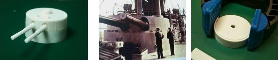
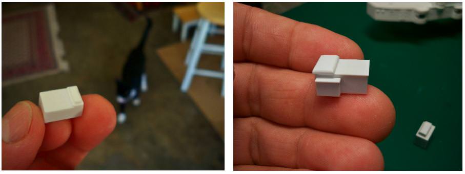
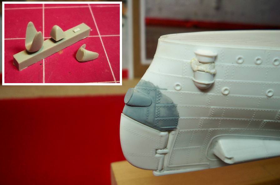
The most serious mistake Revell made with the main turrets was the gun sighting cupolas on the turret roofs. The cupolas are the right size and shape, but they are incorrectly placed. Apparently working from drawings, Revell designers correctly placed the sighting cupola in the center of the each turret as seen from abeam, as in a side-view drawing. However, they must not have had (or not consulted) an overhead view, which would have revealed that there were actually two of these cupolas on each turret roof placed side by side. This is a shame since the Revell parts were nicely rendered, and I couldn’t remove them without damaging them. There were not enough of them to outfit both turrets anyway. An alternative I considered was to resin cast copies and replace the originals, but resin casting is an expensive, messy, and time consuming process I only resort to if I can’t solve the problem in any other way. So I went trolling through my spare parts boxes to find something suitable. The parts boxes yielded nothing, but I finally found a combination that worked: vent tops (parts B-19) form my in-progress Tamiya 1/350 New Jersey were an excellent match for the size and shape of the cupola tops, although I did have to remove them from the half-built battleship (snif) 
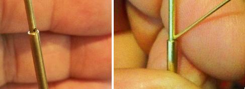
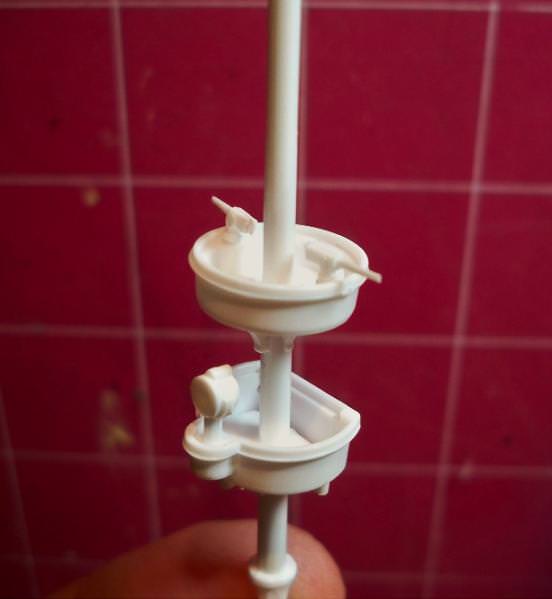
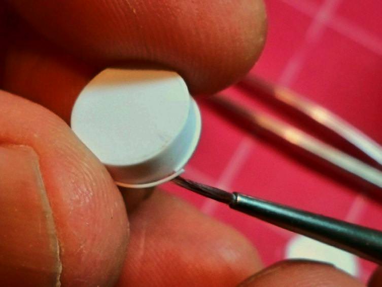
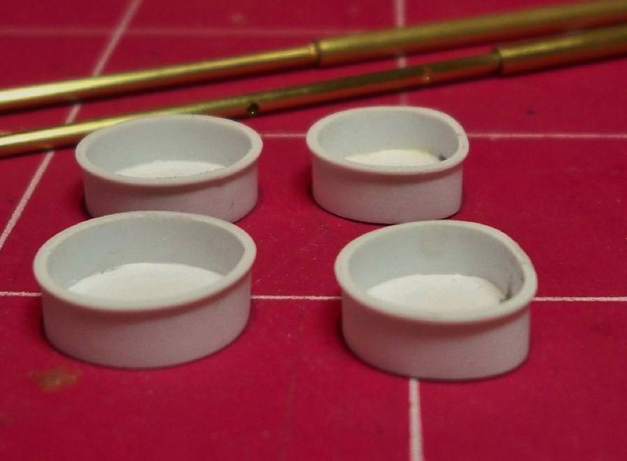
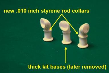
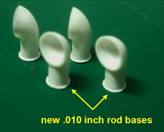
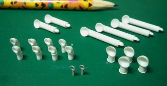
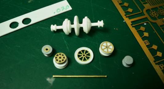
... and even they were too short. Further searching yielded the disc retainers for the main gun mounts on the Varyag kit (parts 61). These were almost exactly the same diameter as the Tamiya parts, and together they brought the new cupolas to the correct height. A further advantage of this solution was that the slight mismatch between the parts left a visible horizontal line on each cupola which neatly replicates the sighting apertures missing from the original Revell cupolas.

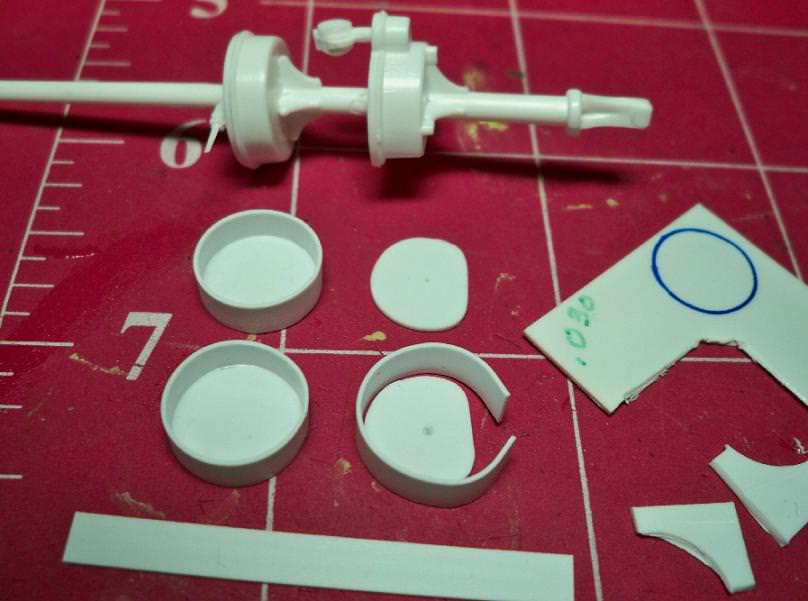
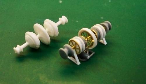
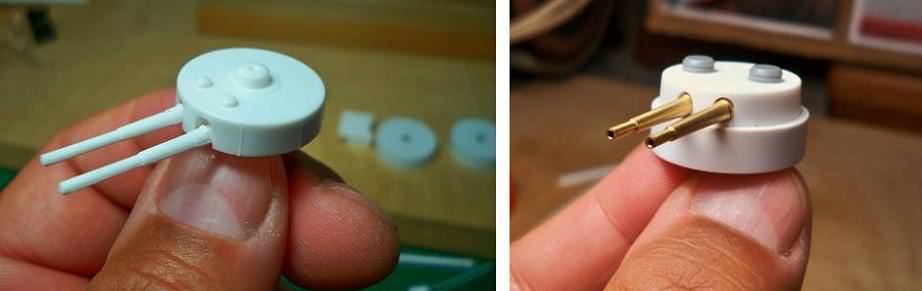
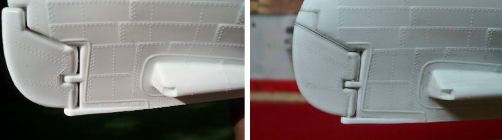
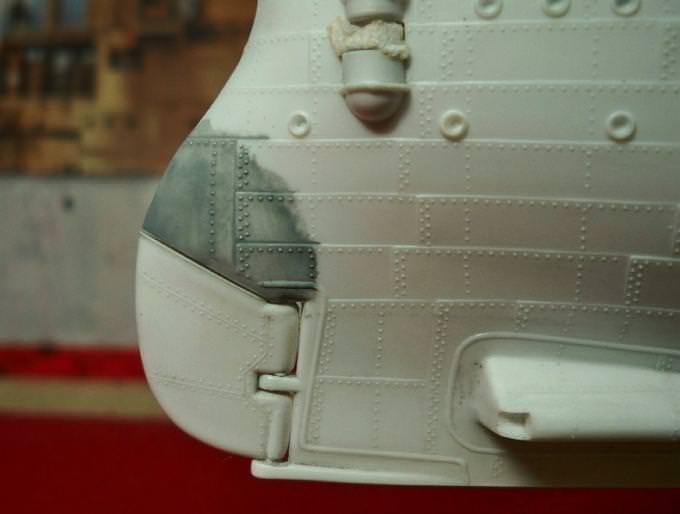
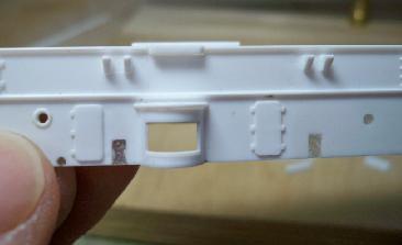
Before setting in those cool B & D turned brass barrels, there was one more detail; relocating the little dome shaped vents on the turret tops. For some reason Revell had placed these forward of the cupolas, but the Booklet of General Plans drawings and photos show these to have been behind them, so I replaced them with plastic discs and put them in their correct locations. These small vents are depicted in the kit as domes, but the few images I was able to find showing this area appear to indicate that the round openings actually had small flat covers which were sometimes (as when in port) removed so that temporary cowl vents could be fitted—without forced air those enclosed steel turrets must have been like ovens!

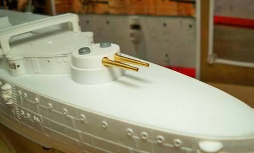
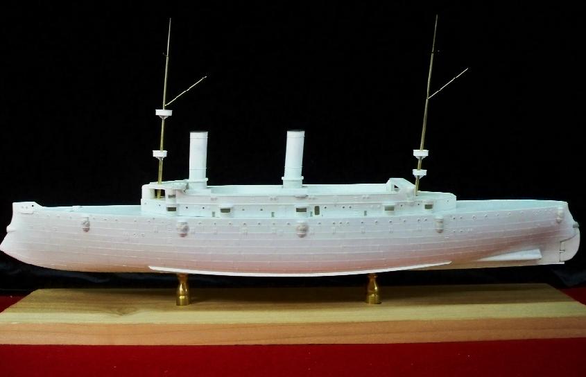
The turrets look better after all this, but even with with the changes they still look pretty plain. I'll affix photoetch toe rails to the roofs later, and no doubt there is additional detail I could add, but close up pictures are hard to come by. I had some great photos of the preserved ship that I thought would provide guidance, but it turns out the original 8 inch turrets were removed before World War One; the ones there now are replicas added in the 1950s when the ship became a museum! So until and unless I get some new information, I'll leave them as they are.
TimReynaga
Staff MemberAssociate Editor
MODEL SHIPWRIGHTS
Visit this Community
California, United States
Joined: May 03, 2006
KitMaker: 2,500 posts
Model Shipwrights: 1,830 posts
Posted: Wednesday, February 15, 2012 - 05:32 PM UTC
A short update this time, one of those smaller details. On the kit, the inboard openings on the gunwales forward where the anchor cables pass over the side are depicted flat, without chafing collars. I made some from Plastruct 0.3mm styrene rod formed into little donuts around a .039 inch punch.


Very simple really, the only challenge (other than not losing track of the tiny things!) being to hide the seams where the ends of the rings connect. Once done and installed they work pretty well. I couldn’t resist trying them out with the anchor chain and a test bit of wood deck just to see how they’ll look:

RussellE
#306
Visit this Community
Victoria, Australia
Joined: June 27, 2010
KitMaker: 3,959 posts
Model Shipwrights: 2,777 posts
Posted: Thursday, February 16, 2012 - 08:23 AM UTC
Great work so far Tim. Really enjoying watching this build.

Russ.
surfsup
Visit this Community
Queensland, Australia
Joined: May 20, 2010
KitMaker: 1,230 posts
Model Shipwrights: 1,212 posts
Posted: Saturday, February 18, 2012 - 07:01 PM UTC
Stunning job so far Tim. Just love your work.....Cheers Mark
TimReynaga
Staff MemberAssociate Editor
MODEL SHIPWRIGHTS
Visit this Community
California, United States
Joined: May 03, 2006
KitMaker: 2,500 posts
Model Shipwrights: 1,830 posts
Posted: Friday, February 24, 2012 - 01:43 AM UTC
Thanks guys! Lately I’ve been working on the mass of ventilators which festoon the Olympia.

The t-shaped box vent was one of the many types found on the ship. These were located on either side of the aft funnel on the superstructure deck. The two kit parts (#40) looked pretty good out of the gate, except that the vent boxes were incorrectly angled to make it easier for the manufacturer to pull the parts trees from the molds. These were an easy fix, just requiring replacement of the lower boxes with straight plastic stock.


The most numerous vents found on the Olympia were the cowl variety, the ship having some twenty of these in five different styles. The parts were for the most part accurately designed and well shaped, but unfortunately mold misalignment (at least in the 1999 reissue of the kit I have) was a problem on almost all of them. I wasn’t looking forward to the unexciting, repetitive task of bringing all these parts up to snuff, but they are so visible that they really need to look right. So with a free evening, the kids entertained with a video (and myself with an ample supply of Mexican beer), I set to work, one vent group at a time...
They all needed attention, but the worst were the eight small main deck vents (parts #23). These parts were well mastered, but after scraping away the heavy mold lines they were too shallow and bereft of detail. Worse, all that scraping had distorted the shapes, so I repaired them by building up the low areas with cyanoacrylate and then sanding them back into proper profile. To restore the round openings I added .010 inch sheet plastic to the cowl faces, which were then re-shaped into circles. Then I hollowed them out (deepening the vent mouths as well, since the original parts were just a bit shallow) using a small Dremel round grinding bit. The little collars two thirds of the way up, which were nicely mastered but ruined by misalignment, were removed and then reconstructed using Plastruct .010 inch round styrene rod. Finally the vent bases, which at first looked fine to me on the kit parts, turned out to be far thicker than the originals on the ship, so I sanded them away.


The four fat deck vents to be fitted to the center of the boat deck (parts #56) needed only basic clean up, but these bases also looked too thick, so I replaced them with .010 inch rod. Much better.


I removed and replaced the over large bases on the six tall vents on the boat deck (parts #62 and #68) as well. They also got new .010 inch rod collars to repair the misaligned kit representations. This was worthwhile also since those molded on the kit parts were placed too low; the new ones are in the correct locations a little higher up. By the way, these “collars” were actually connection points between the lower fixed upright vent tubes and the moveable cowls fitted at the tops, which were positionable to better face into breezes to vent the ship. My depiction of these connections, as with Revell’s, is just a little exaggerated, but I did them this way to better harmonize with the somewhat heavy detailing found throughout the kit. I also added a couple of smaller vents (the gray ones in the picture, taken from the Varyag) which Revell had overlooked.


Whew! Now that these little *&%$@!#s are in the bag I hope to get on to more interesting parts of the build this weekend. College financial aid seminar with my oldest daughter last night, Girl Scouts with the eight year old at home (the wife is troop leader) and my son’s basketball tonight... but the kids’ll be away over the next couple of days, so I plan to get some modeling time in!

Have a great weekend yourselves!

Tim
MrMox
Visit this Community
Aarhus, Denmark
Joined: July 18, 2003
KitMaker: 3,377 posts
Model Shipwrights: 985 posts
Posted: Friday, February 24, 2012 - 04:49 AM UTC
Il like the work you put into this old lady, she is going to look great when done!

Cheers/Jan

TimReynaga
Staff MemberAssociate Editor
MODEL SHIPWRIGHTS
Visit this Community
California, United States
Joined: May 03, 2006
KitMaker: 2,500 posts
Model Shipwrights: 1,830 posts
Posted: Saturday, February 25, 2012 - 02:57 AM UTC
Man, after all those vents I thought I was done with them, but here are a couple more!


On the left is the unmodified kit part #38 (“water tank”) which is supposed to go on the boat deck between the funnels. The kit part has the right basic shape and dimensions, but it is seriously lacking in detail; the piece is so indistinct you can’t really tell what it is. Since it will be located in a very visible area, I scratchbuilt a better one. The new water tank (right photo) has a more distinct cover and the missing vent boxes on the sides. In the background on the second shot is the scratchbuilt replacement for the other vent box (part #41) which will go between the aft funnel and the main hatch/skylight.
RedDuster
Visit this Community
England - South East, United Kingdom
Joined: March 01, 2010
KitMaker: 7,078 posts
Model Shipwrights: 6,649 posts
Posted: Sunday, February 26, 2012 - 10:19 PM UTC
Hi Tim,

Looks like those vents were "fun".

great work thought.

Si
TimReynaga
Staff MemberAssociate Editor
MODEL SHIPWRIGHTS
Visit this Community
California, United States
Joined: May 03, 2006
KitMaker: 2,500 posts
Model Shipwrights: 1,830 posts
Posted: Tuesday, February 28, 2012 - 03:32 PM UTC
After all those vents I was glad to work on something a little more interesting: the ship’s windlass. Located on the superstructure deck aft of the funnel, the windlass will be partially obscured on the final model by ship’s boats mounted in the racks above it, which is most likely why Revell didn’t bother to give it much attention. The kit part is accurate in a general way, but crude. Still, it is an interesting looking piece of equipment, and there are some good reference photos of the real one on the Internet. So even though it is only about an inch long, I thought it would be cool to do it up right.


Starting with a .028 inch Albion Alloys brass tube for the axle, I built it up in sections. The gray outer warping drums are anchor capstans (parts #20) from the Zvezda Varyag kit with liferings from a Gold Medal Models 1/400 scale German WWII warships set applied on the inside. Then came discs of .020 inch plastic stock, alternating various diameters to build up the structures. The open spoked wheels used to detail the outermost drums were photoetched brass parts from the Tom’s Modelworks Olympia set. The gray drums were adapted 20mm gun positions from a 1/700 Tamiya King George V, and the brass drum faces attached to them towards the inside of the winch were photoetched N-Scale brake wheels from a Gold Medal Models freight car detailing set (set #160-23). The central open spoked flywheel was a photoetched Bismarck/Tirpitz capstan part from the GMM German warships set. This wheel was set into a .020 inch plastic disc made with an office hole punch and hollowed out to form a ring. This then had a .010 X .040 inch Evergreen plastic strip applied around it. Supports were built up from .015 X .040 and .010 X .060 inch plastic stock. The motor mechanism underneath was an adaptation of a 1/350 Revell Emden lifering rack with plastic discs and an operating lever made from telescoping 0.6mm and 0.8mm Albion Alloys brass tubes.


Now that was fun!

best,
Tim
surfsup
Visit this Community
Queensland, Australia
Joined: May 20, 2010
KitMaker: 1,230 posts
Model Shipwrights: 1,212 posts
Posted: Friday, March 02, 2012 - 12:30 PM UTC
Love those Winches my Friend. Looking great.....Cheers mark
TimReynaga
Staff MemberAssociate Editor
MODEL SHIPWRIGHTS
Visit this Community
California, United States
Joined: May 03, 2006
KitMaker: 2,500 posts
Model Shipwrights: 1,830 posts
Posted: Tuesday, March 06, 2012 - 04:41 PM UTC

Quoted Text

Mr. Reynaga,
Will you be addressing the rudder issue? When I built mine 25 or so years ago, I took the simple expediant of slicing off the extension, gluing it to the cut-out in the hull, and filling and sanding.

http://www.navsource.org/archives/04/c6/c0646.jpg

I have to say yours is WAY better than mine ever was!
Best regards,
Alan
amillen at seic dot com


Ok Alan, you got me! Despite my best efforts to save the extra work, I just couldn’t find a way to justify Revell’s weird rudder with that odd little extension (left picture), so I had to go back and fix it. Made the correction as you suggested, which worked fine.


I can’t fathom what those Revell designers were thinking. Interestingly, if you look closely at the unaltered kit part (in the first picture), you can see a raised line across the rudder top where it should be cut. I guess they just misinterpreted whatever design drawings they were working from.


Anyway, it was a simple repair that disappears under a little primer.

Thanks again for the advice!

Tim
TimReynaga
Staff MemberAssociate Editor
MODEL SHIPWRIGHTS
Visit this Community
California, United States
Joined: May 03, 2006
KitMaker: 2,500 posts
Model Shipwrights: 1,830 posts
Posted: Thursday, March 08, 2012 - 03:09 AM UTC
After I made the post about fixing the rudder yesterday, the new Encore (Squadron) "Premium Edition" Olympia re-release appeared on my porch. Among the resin upgrade parts in the new issue is a little piece to correct the rudder and outer covers for the torpedo tubes fore and aft. Now that I've already fixed the rudder I won’t need the the correction piece, and the kit already has an acceptable cover molded forward. The aft torpedo cover, however, is most welcome. Revell had included the launcher cover at the bow in the original molding but not the one on the stern. This configuration matches the museum vessel’s present appearance and is accurate for Olympia after her November 1899–January 1902 refit. Unfortunately, it isn’t correct for the Spanish-American War Olympia the Revell kit otherwise represents. The wartime ship had tubes fore and aft with both outer covers still in place.

Anyway, the aft torpedo tube cover part is very well executed, and when I test fitted it this evening it matched the kit hull perfectly!
Alanroy
Visit this Community
Pennsylvania, United States
Joined: March 27, 2006
KitMaker: 65 posts
Model Shipwrights: 2 posts
Posted: Monday, March 12, 2012 - 12:27 AM UTC
Looking very good! I've only finished one model in the last 15 years, and that one only because it was for my Father-in-Law's 75th birthday. He was the catapult officer on the Essex-class Princeton in 1951-52, during the Korean War. Between work and owning a fixer-upper, the time just isn't there. I've had the Olympia in the stash for over 30 years now. Whine, whine, whine.
Best regards,
Alan
JForeman
Visit this Community
United Kingdom
Joined: March 12, 2012
KitMaker: 2 posts
Model Shipwrights: 1 posts
Posted: Monday, March 12, 2012 - 08:25 AM UTC
I have just come across your build so as well as re-doing mine to up the standard, have joined the group. To make the model more interesting, mine will have all the port side casements closed and all the starboard open. I figured it would save making half the guns and modifieng half the casement ports. Do you think the rear QF casements in the hull are correct? I think they stick out so to make the molding simpler.
I was luckey and visited the Olympia a couple of years ago while on holliday. The whole ship to myself. I do hope they get the problems sorted.
kurt4394
Joined: January 28, 2007
KitMaker: 17 posts
Model Shipwrights: 5 posts
Posted: Monday, March 12, 2012 - 01:11 PM UTC
Really enjoying this thread. I love your solutions for correcting the kit. I just received the new Encore kit. Wish I had your spare parts box to go with it! I ordered a set of plans from Floating Drydock to help. I live about an hour from the Olympia and was on her with my son this fall. It was amazing how small it is. I can't imagine how it held her crew. I couldn't stand up in the armored command center, its only about 5 1/2 feet tall! I really hope they can save her and not scrap her. Looking forward to your progress.

Kurt
TimReynaga
Staff MemberAssociate Editor
MODEL SHIPWRIGHTS
Visit this Community
California, United States
Joined: May 03, 2006
KitMaker: 2,500 posts
Model Shipwrights: 1,830 posts
Posted: Tuesday, March 13, 2012 - 03:46 AM UTC
Alan, John, and Kurt—

Thanks for your comments guys, I always enjoy hearing other modelers’ perspectives.

Alan, I know what you mean, my modeling output too is frustratingly low! After work, family, the house, and everything else, there just don’t seem to be enough hours in the day—although I can’t beat your record of having an unbuilt model for 30 years! With all the aftermarket upgrades now available, it is high time to break your Olympia out of the stash...

John, in answer to your question, yes, I believe the aftermost QF casemates do stick out a bit too much; in fact, comparing the model with photographs of the museum ship suggests that all the casemates on the hull are somewhat overstated. I decided not to correct mine as it would have been a major effort to remove, rebuild, and replace all ten of them, and I like them well enough as they are. Like the overdone plate and rivet detail on the hull, I reckon the exaggerated casemates, though not precisely accurate, will contribute to a pleasing “impressionistic” effect on the finished model. At least that is my hope!

Kurt, I haven’t seen the Floating Drydock plans, but I’ve been using the1895 Booklet of General Plans (available free online through the Historic Naval Ships Association at http://www.hnsa.org/doc/plans/ ) and historical photographs, as well as pics of the preserved ship. I’m envious of you guys who have been able to visit the Olympia; talk about the ultimate reference! Philadelphia is across the country from me and I’ve not yet had the opportunity.
Your comments about the tiny armored command center are interesting; makes me think of poor Captain Gridley who fought the ship from in there for hours under the hot Philippine sun during the Battle of Manila Bay. Already sick when the battle began, he died about a month later; he might well be considered a casualty of the battle.

Anyway, glad to hear you picked up the Encore (Squadron) re-release. It is nice, isn’t it? I hope you went for the “Premium Edition” with all the upgrades. The wood veneer decks, photoetch, and resin parts are very good indeed. I got my copy last week, started with the resin torpedo tube cover aft. The part is well designed, integrating neatly into the hull just above the waterline. Next to no filler was needed to install this simple correction for the Revell kit.

Way to go Squadron!

best regards,
Tim
SBrown
Visit this Community
Massachusetts, United States
Joined: March 16, 2012
KitMaker: 2 posts
Model Shipwrights: 1 posts
Posted: Friday, March 16, 2012 - 04:24 AM UTC
Hi Tim,

The Olympia Premium Edition arrived at my front door yesterday, and I can't wait to get started! I put the hull halves together (dry fit, no glue)and after lashing them together with scotch tape I can see that some puttying / sanding will be required. Do you have any suggestions for seam filling? I looked into different brands of modeller's putty, but I found that

"They do not bond with resin or metal" (http://www.scalemodelguide.com/guide/construction/about-fillers/)

Yikes. I have visions of cracked putty at the bow/stern torpedo tubes, the PE bilge keels popping off, and God knows what else if the wrong sealant is used Any information or advice would be really appreciated! Your build looks incredible, by the way, and I really admire the level of detail you have put in to it. Thanks for sharing!

Steve
TimReynaga
Staff MemberAssociate Editor
MODEL SHIPWRIGHTS
Visit this Community
California, United States
Joined: May 03, 2006
KitMaker: 2,500 posts
Model Shipwrights: 1,830 posts
Posted: Friday, March 16, 2012 - 07:31 AM UTC
Hi Steve,

Thanks for your kind words. I'm doing quite a bit of rework on my Olympia model, but it is by no means necessary. The basic Revell kit is quite good on its own, and you can get a really nice result using only what Squadron has provided in the Premium Edition box. It's just that I made a few minor corrections in the beginning, and before I knew it things got completely out of hand...

Anyway, as for seam fillers, I use different fillers for different situations. My favorites are cyanoacrylate (super glue) and Squadron Green Putty.

Cyano can be difficult to control and is unforgiving if you get it on detail you want to keep (like when I spilled some on one of the Olympia's superstructure doors), but it also offers advantages. If you use a cyano accelerator it is fast drying, and when dry it can be worked just like polystyrene plastic. Cyano doesn't shrink, has low to no toxicity, and it is tough and very stable over time. It can be quite effective as a filler. I used cyano to fill those gaping rectangular holes for the large boat davits on the superstructure sides, for example:

Best of all, cyanoacrylate is great for bonding metal, wood, and resin to plastic. I used cyano to attach the resin torpedo tube cover to the plastic hull. It would also be great for attaching the metal bilge keels to the plastic hull.

Another filler I use is Squadron Green (or White) Putty. This stuff is a nasty, smelly and highly toxic goo, but it has advantages too. Because it can be thinned, it can be easily controlled. I use the stuff by squeezing a dab onto a palette (such as the lid from an old margarine container) and thinning it with Testors liquid plastic cement. The resulting slurry can be applied with a paintbrush either over relatively large surfaces (like the main deck to hull join) or into very small corners with a fine brush. It shrinks slightly as it dries, which can be useful for many types of seams. It integrates really well with the plastic since it welds it chemically (as opposed to glues, which merely stick). Use it with restraint, though; the down side is that this stuff can dissolve your model if you use too much! Also, it is not all that strong, so I only use it to fill fairly small gaps between plastic parts. It won't work on metal or resin since it doesn't react chemically with them.

I also occasionally use JB Weld two part liquid epoxy for filler, but more often as a glue when I want a VERY strong bond. I used this stuff on the inside of Olympia's hull to attach the retaining bolts for the brass pedestals, and also to attach the brass mounting sleeves for the masts to the plastic decks.

I hope all this was of some use to you; we all have our individual preferences. Try different materials and play around with techniques— you'll get a sense of what works best for you in no time. Good luck with your Olympia!

regards,
Tim
Removed by original poster on 03/25/12 - 15:22:52 (GMT).
TimReynaga
Staff MemberAssociate Editor
MODEL SHIPWRIGHTS
Visit this Community
California, United States
Joined: May 03, 2006
KitMaker: 2,500 posts
Model Shipwrights: 1,830 posts
Posted: Sunday, March 25, 2012 - 05:45 AM UTC
With the hull, superstructure, and other major components mostly done, it’s time to tackle the masts. The kit provided parts are not too bad, but they are a little heavy and have some inaccuracies. Rather than try to fix them I opted to just replace them with brass tube. The brass is a bit more work, but it is worth it since the metal is stronger and straighter than the plastic parts, and is also perfectly round with no molding seams. Using the kit assemblies as patterns (which, happily, correspond closely with the Booklet of General Plans drawings), I built the masts up in telescoping sections.

The lower portions were replaced with K & S #1268 3/32 inch X .014 inch (23.8mm X .355mm) brass tube, followed by K & S #1251 1/16 inch X .014 inch (1.57mm X .355mm) tube and finally Detail Associates #2509 .33 inch brass wire for the upper portions. These tubes fit neatly into each other to taper the masts from base to top. The completed masts were then glued together and placed in sleeves (which won’t be visible on the final model) made from sections of K & S #127 1/8 inch X .014 inch (3.18mm X .355mm) brass tube. These sleeves, which will determine how the masts will ultimately sit, were set into holes cut through the plastic deck and lightly secured in place with plastic cement. Temporarily setting the masts into the sleeves while the cement was still uncured, I adjusted them, checking constantly against plans and making sure the masts were set at the correct angles while also being laterally perpendicular to the deck and parallel to each other.
]
When all seemed well, I slipped the masts from the mounting sleeves. After allowing the plastic cement holding them to the decks to dry, I fixed the sleeves permanently in place with JB Weld two-part epoxy. Now I could be sure the final masts would be secured at the correct angles when they go back in place later on.
[

Next, I made the yardarms and gaffs using Detail Associates #2508 .028 inch brass wire following the kit parts for the dimensions. Attaching the spars will be no problem as they fix to the masts at junctions between widths of tube and can be securely super glued at the steps. As for the gaffs, they mount at angles so just gluing them to the masts would likely not have been sufficiently strong; I drilled small holes in the masts to accommodate them so they can be super glued in place to assure a firm bond. Along with the spars, I’ll fix them to the masts after the searchlight platforms and fighting tops are in place.

Next up: searchlight platforms and fighting tops
surfsup
Visit this Community
Queensland, Australia
Joined: May 20, 2010
KitMaker: 1,230 posts
Model Shipwrights: 1,212 posts
Posted: Sunday, March 25, 2012 - 07:30 PM UTC
Getting better and better each time I see her Tim.....Cheers Mark
TimReynaga
Staff MemberAssociate Editor
MODEL SHIPWRIGHTS
Visit this Community
California, United States
Joined: May 03, 2006
KitMaker: 2,500 posts
Model Shipwrights: 1,830 posts
Posted: Tuesday, March 27, 2012 - 03:44 PM UTC
The searchlight platforms and fighting tops provided in the original Revell kit look reasonably good, if a little heavy. They are the correct sizes, the searchlights are decent, and the 1-pounder guns are not bad at all.


On the other hand, the searchlight platforms have the lights mounted on incorrect little pulpits jutting out from the platforms. In reality, the platform faces were round and the lights sat on mounts inside them. Also, the four supports underneath each platform are depicted fore-and-aft and beam-to-beam, but they were actually angled off the centerline and beams.

My first plan had been to correct and improve the kit parts, but with the new masts it seemed simpler to just replace the platforms as well.

I began with bases of .030 inch round plastic, cut out using a circle template to get consistent round shapes of the right diameter. All started the same, with the two searchlight platforms then having sections trimmed from one edge to flatten them on one side. The fighting tops remained round. Strips of Evergreen .015 X .156 inch plastic stock were then cemented around them to form the shields. They were finished off with narrow bands of Plastruct #90709 .010 inch square plastic strips added to replicate the thicker upper edges of the platform shield tops evident in photos.

Next I drilled holes in the centers of the completed platforms and slipped them on to the masts. They were then lightly attached with liquid plastic cement. They had to be set on the slanted masts at angles in order to be parallel to the deck (and to each other), so I dry-fit the masts onto the ship to check things and make adjustments as the cement dried.

When all was satisfactory I set the platforms securely in place with cyanoacrylate and removed the mast/platform assemblies from the ship.To complete the platforms, I added four small triangular supports underneath each one. Very nice looking replacements for these are provided in both Tom's Modelworks and the Squadron/Encore photoetch sets, but unfortunately they have incorrect lightening holes in them, do not fit very well, and are too thin. I made new ones from .015 inch plastic stock and attached them with cyano.

With the addition of the previously prepared spars and gaffs, the basic mast assemblies were complete.

RedDuster
Visit this Community
England - South East, United Kingdom
Joined: March 01, 2010
KitMaker: 7,078 posts
Model Shipwrights: 6,649 posts
Posted: Tuesday, March 27, 2012 - 09:02 PM UTC
Coming well Tim, the new masts and platforms look the bussiness.

What will you use to rig her?

Si
MrMox
Visit this Community
Aarhus, Denmark
Joined: July 18, 2003
KitMaker: 3,377 posts
Model Shipwrights: 985 posts
Posted: Tuesday, March 27, 2012 - 10:25 PM UTC
I just can´t help being impressed how you bring that old kit back to life - very inspiring.

Cheers/Jan
surfsup
Visit this Community
Queensland, Australia
Joined: May 20, 2010
KitMaker: 1,230 posts
Model Shipwrights: 1,212 posts
Posted: Tuesday, March 27, 2012 - 11:55 PM UTC
I agree with Jan. Very impressive work.....Cheers Mark