_GOTOBOTTOM
General Ship Modeling
Discuss modeling techniques, experiences, and ship modeling in general.
Vosper MTB build
TAFFY3
Visit this Community
New York, United States
Joined: January 21, 2008
KitMaker: 2,531 posts
Model Shipwrights: 1,244 posts
Posted: Thursday, February 09, 2012 - 02:35 AM UTC
This is my first attempt at a Blog. It is going to be a sloooow build due to my approach to doing it. The Italeri kit is very good, but leaves a lot of room for additional detail. Particularly in the wheelhouse, and inside the gun turret. Additional armament can also be added. The model is MTB 77, which was later up-gunned with a captured Italian 20mm Breda cannon. Different combinations of 20mm Oerlikon guns, and .303 Vickers and Lewis MG's were also mounted on other boats.

I don't always follow the recommended order of assembly during a build. The first thing I did was complete the hull by adding the stern plate and rub rail. The rub rail required some putty to blend it in. I've found that with all of the Italeri boats in this series, the fit of parts is excellent and very little putty work is required.

The stern plate fitted:


The rudders and props were also added. I replaced the prop shafts with brass rod for strength.

A view of the boat with some assemblies temporarily in place:


The instructions would have you add the wheelhouse top, back, and sides separately to the deck. I assembled mine as a complete unit to be added later.

The completed wheelhouse:


I also included some extra detail in the wheelhouse:


The wheelhouse top and sides fit together well the only visible seam will be hidden by the spray shield around the top. Due to AMS I will probably putty it anyway. Al
TAFFY3
Visit this Community
New York, United States
Joined: January 21, 2008
KitMaker: 2,531 posts
Model Shipwrights: 1,244 posts
Posted: Thursday, February 09, 2012 - 02:53 AM UTC
Please excuse the links instead of the actual pictures. I'm very inexperienced at the proper use of a computer (read Dinosaur). I now understand the problems my father had programming a VCR (again, read Dinosaur). I'll have to wait 'til my son gets home so he can show me how to post pictures instead of live links. I suppose it is a minor victory that I can post the links at all. Al
(P.S.) for you youngsters, a VCR is what we had before DVD's and BlueRay (read Dinosaur)
Gremlin56
Joined: October 30, 2005
KitMaker: 3,897 posts
Model Shipwrights: 3,301 posts
Posted: Thursday, February 09, 2012 - 04:45 AM UTC
A big thumbs up Al, looking good ! I'll be following your first blog
Cheers,
Julian
TAFFY3
Visit this Community
New York, United States
Joined: January 21, 2008
KitMaker: 2,531 posts
Model Shipwrights: 1,244 posts
Posted: Thursday, February 09, 2012 - 05:41 AM UTC
Thanks Julian, I've actually gotten quite a lot done before deciding to start this Blog. As soon as I've spoken to my tech support (AKA my son) I'll post some more pictures.
My single biggest gripe so far is that Italeri chose to mold the cleats for the halyards onto the side of the wheelhouse. How they expect you to tie lines to them I'm sure I don't know. There are some tiny handles for the hatches which are separate pieces, why not the cleats? I know they want to keep costs down, but would that really increase the selling price? Al
TAFFY3
Visit this Community
New York, United States
Joined: January 21, 2008
KitMaker: 2,531 posts
Model Shipwrights: 1,244 posts
Posted: Thursday, February 09, 2012 - 12:06 PM UTC
I opened the exhaust ports and added tubing for depth:


There were two small ejection pin marks on the three exhaust ports that needed to be filled. Al
TAFFY3
Visit this Community
New York, United States
Joined: January 21, 2008
KitMaker: 2,531 posts
Model Shipwrights: 1,244 posts
Posted: Thursday, February 09, 2012 - 12:24 PM UTC
In many photos of Vosper MTB's in port, the foredeck hatch is shown open. There is a cutaway drawing in the Osprey book, British MTB's, that shows a bulkhead with a ladder and hatchway. I decided to add these details as a partial interior.

The bulkhead:


The bulkhead, deck, and forward bulkhead taped temporarily in place:


The ladder seen through the forward hatch:


The four sockets at the corners of the hatch were used for a frame for a canvas wind dodger. They were molded just as little bumps so I drilled them out. Al
TAFFY3
Visit this Community
New York, United States
Joined: January 21, 2008
KitMaker: 2,531 posts
Model Shipwrights: 1,244 posts
Posted: Thursday, February 09, 2012 - 04:06 PM UTC
The Torpedo tubes in progress:


I added the saddle mounts for the twin Vickers .303 MGs to each tube. They were inspired by another builders work seen elsewhere on Model Shipwrights, Thank you Tom. They weren't as difficult to make as I thought (feared) they would be.

Close-ups of the mount:


I also made a couple of storage bins for the Vickers' ammo drums.


Due to the positioning of the ammo bins I had to move the life preservers to a new spot on the wheelhouse. You can see the new locating holes and the filled-in originals. There seems to have been some variation in their placement among the different boats. In fact, the photo of MTB 77 in the included reference booklet shows the life rings in a different location than the kit would have them. Al
RedDuster
Visit this Community
England - South East, United Kingdom
Joined: March 01, 2010
KitMaker: 7,078 posts
Model Shipwrights: 6,649 posts
Posted: Thursday, February 09, 2012 - 09:14 PM UTC
Looking Good Al.

Nice to see another Vopser on the go. Like all the additional detail in the wheelhouse and round the Vickers mounts.

Are you going to mount the Breda?

I am looking at building mine as another Breda fitted boat, MTB 84, but that is a summer project, as it is bit too big for my work cupboard, I mean room.

following with much interest.

Si
TAFFY3
Visit this Community
New York, United States
Joined: January 21, 2008
KitMaker: 2,531 posts
Model Shipwrights: 1,244 posts
Posted: Friday, February 10, 2012 - 01:38 AM UTC
Hello Simon, Thanks, I do want to mount a Breda and I am hoping to find a picture or two of how it was mounted on the boats. I would imagine the British captured more guns from the Italian Army than their Navy. So, I'm wondering if they were modified, or just bolted down, or what? I'll have to order the gun from my local hobby store. The kit comes with a small trailer, pulled by a mule, with two figures. I'm waiting to see what that ground mount looks like. Knowing how things usually turn out, I'll probably just have to take my best guess on mounting it. Then the photos proving me wrong will turn up. Al
TheModeller
Visit this Community
England - South East, United Kingdom
Joined: March 01, 2010
KitMaker: 127 posts
Model Shipwrights: 43 posts
Posted: Friday, February 10, 2012 - 02:02 AM UTC

Quoted Text

Hello Simon, Thanks, I do want to mount a Breda and I am hoping to find a picture or two of how it was mounted on the boats. I would imagine the British captured more guns from the Italian Army than their Navy. So, I'm wondering if they were modified, or just bolted down, or what? I'll have to order the gun from my local hobby store. The kit comes with a small trailer, pulled by a mule, with two figures. I'm waiting to see what that ground mount looks like. Knowing how things usually turn out, I'll probably just have to take my best guess on mounting it. Then the photos proving me wrong will turn up. Al


Take a look at this picture Al, I found it on Flickr taken at the Croation Maritime museum.

http://www.flickr.com/photos/25063579@N08/3260745816/

I don't know anything more about it than this, there is also a single image of an unmounted Breda in Reynolds 'Mediterranean MTBs at War'.

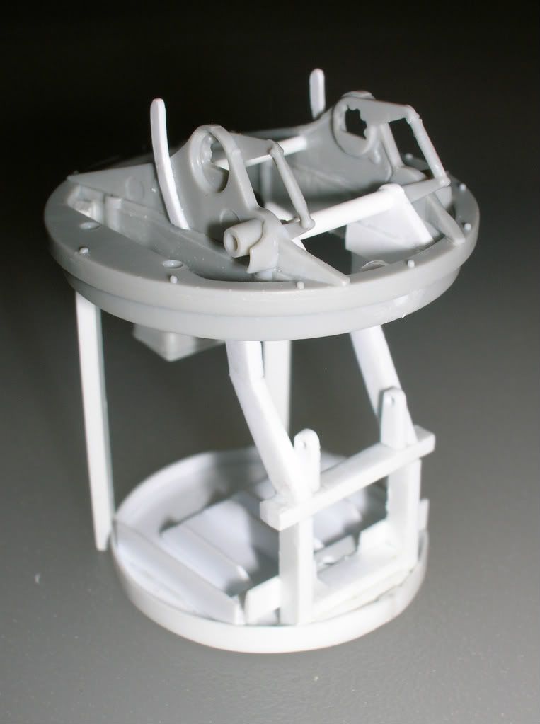
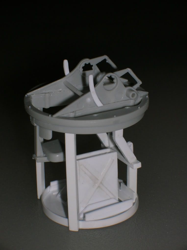
The pivots for the trail legs seem to be welded to a circular mounting ring, in turn bolted down, I can't tell if this is a mount constructed just for the museum display but if I had a complete Breda in my museum I don't think I'd chop it up just to put it on a concrete pedestal. I think the mount is 'original', at least as original as anything else!

In the absence of any clear pictures I'm going to knock up the same sort of thing to mount the Breda on my model, oddly enough I'd decided on MTB-84 as well! Its the only one with both the gun and an interesting paint scheme!

I agree with your assessment of the kit, its a nice piece of work, mine is about at the same stage as yours, I had a lot of trouble getting the hull strakes to fit cleanly and spent a couple of nights filling and tidying them up, the port torpedo flute in my kit seems to be more thickly moulded than the starboard one, that needs some attention, and just about every part so far has required either sink or ejector-pin marks filled and cleaned-up!

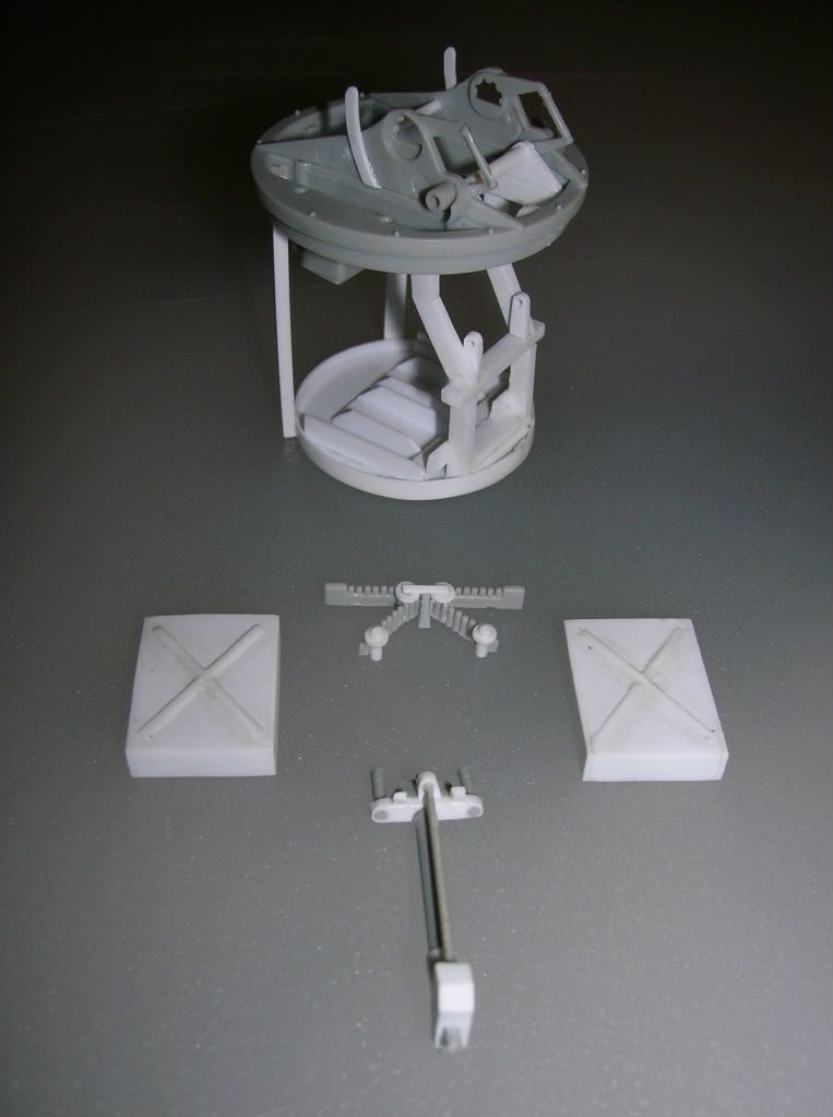
When you build the depth-charge racks you'll notice more bolt-head detail on one pair than the other.

My recommendation is to throw the depth-charge halves in the bin and make new bodies from 1/2" brass or plastic tubing, it's a lot easier! 4 lengths of 21mms and bevel the ends to take the caps from the kit.

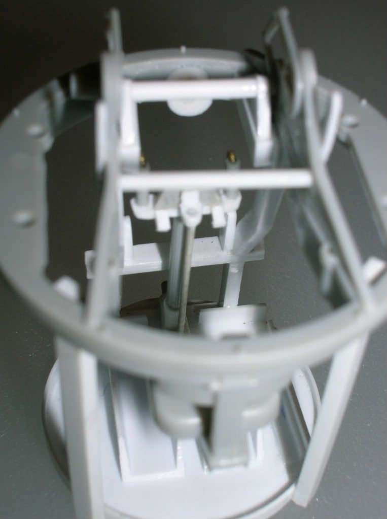
The racks are a fiddle to assemble and get them square, if you have a length of 1/2" tubing cut a piece as above and use it as a jig to support the rack assembly while the glue sets.

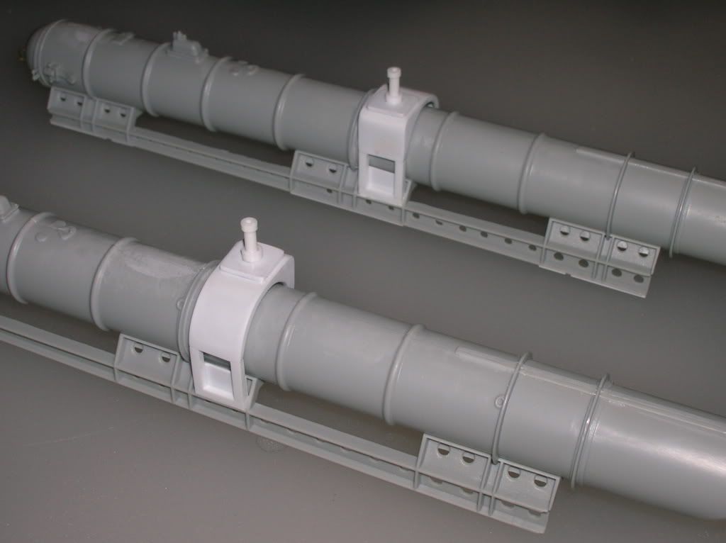
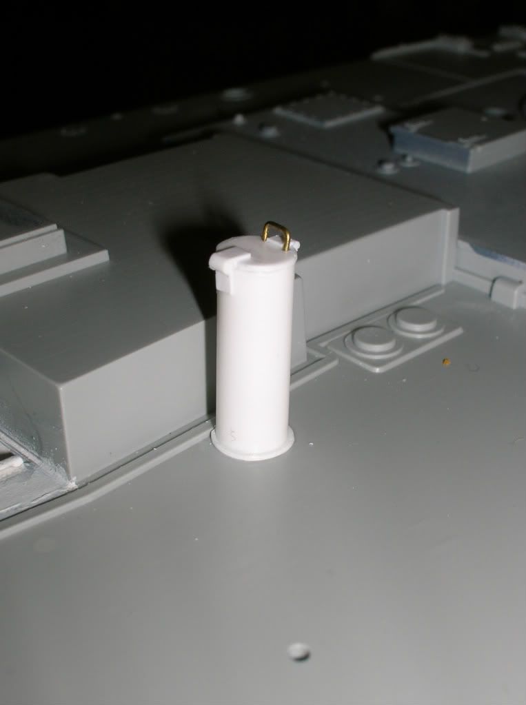
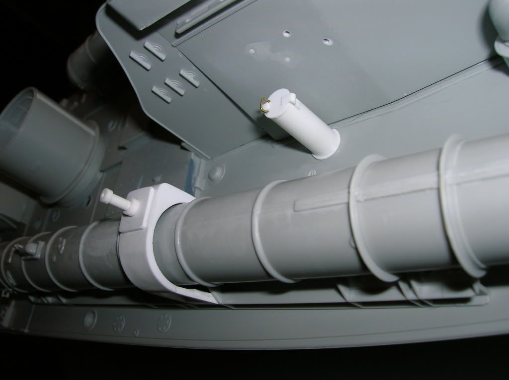
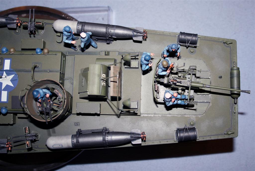
Along with the silly moulding of the cleats on the spray-shield the torpedo tubes are lacking in a lot of bolt-head detail at thier joins and the deck mounts.

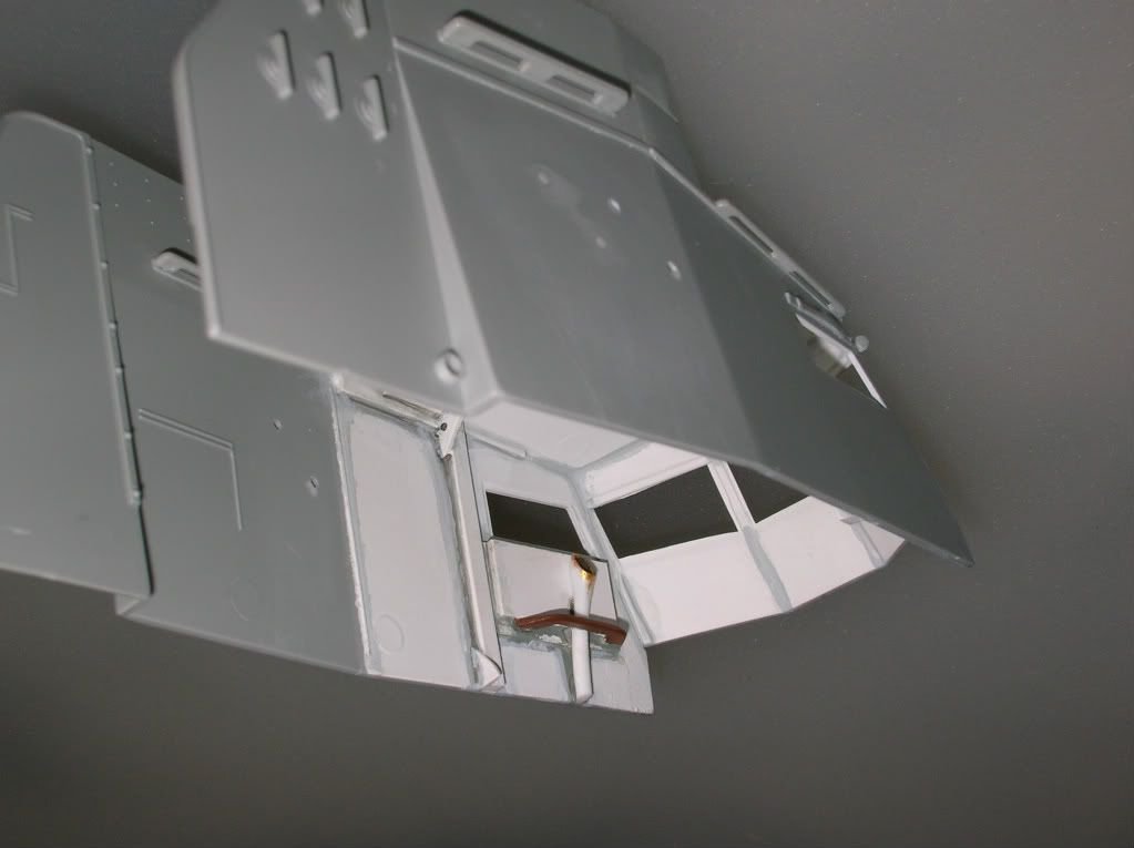
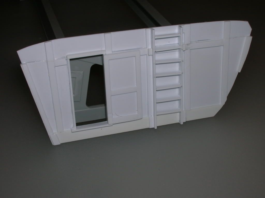
I wanted my engine room shutter doors closed, they aren't wide enough to fit across the opening.

Every last one of the lage intake bell-mouths has needed filling and fettling to take care of the seams and more sink marks.

It'll be a lovely model once it's built but I was expecting a bit more quality in the mouldings for £100!
TAFFY3
Visit this Community
New York, United States
Joined: January 21, 2008
KitMaker: 2,531 posts
Model Shipwrights: 1,244 posts
Posted: Friday, February 10, 2012 - 03:36 AM UTC
Thanks Les, that photo is just what the doctor ordered. I think you're right about this being the way the guns were mounted. It makes sense to me to do it that way.
I bought a couple of pairs of depth charges made by U-model of France for my Elco. I'm wondering if they would work for the Vosper. They are very nicely detailed.
Have you tried adding some plastic strip to the edges of those doors to widen them? That might work if the gaps aren't too big.
I agree that there is lots of room for improvement with this kit and it ain't cheap. But, when you look at the prices that some of the 1/350th scale ships are going for, I think the cost could have been a lot higher for this kit. There is a lot of plastic in the box, and plastic is dependent on oil, and you know how that effects the price. I haven't run into any problems that really make me regret buying it. Compare the Vosper with the Lindbergh PT boat. I bought that kit when it first came out 30 years ago. I returned it as soon as I opened the box and looked inside. That kit was a dog then, and it still is, at better than twice the original price! I can deal with some missing details and simple fixes, as long as I'm not going crazy trying to make everything fit, and using a ton of putty to do it. Al
TAFFY3
Visit this Community
New York, United States
Joined: January 21, 2008
KitMaker: 2,531 posts
Model Shipwrights: 1,244 posts
Posted: Friday, February 10, 2012 - 07:57 AM UTC
For me, one of the focal points of a warship model is the armament. The kits guns are nice, but the turret itself is pretty empty. Here are some pictures of work done to add more detail to the turret.

The turret basket:


With one of the ammo boxes in place:


The turret, ammo boxes, ammo belt, and the control column:


The control column in place:


I was more than a little leery about taking on the challenge of doing this kind of scratch-building, but I'm quite happy with the way it all turned out. While it may not be 100% accurate, I think it makes the turret a lot more interesting to look at. Al
tomdekruijff
Visit this Community
Zuid-Holland, Netherlands
Joined: December 17, 2004
KitMaker: 100 posts
Model Shipwrights: 99 posts
Posted: Friday, February 10, 2012 - 09:02 AM UTC
Hi AL ,

I see that your doing alot more interiour that i'm.
It looks great,i missed sliding sidewindows .
I noticed them to late ,didn't want to start over.
I'll come and watch your progress .
Keep going it's going to be a good one.
TDK.

I looked at your turret more closely and you have 1 of the firing levers on the wrong side of the gun mount. Afaik they didn't change the firing mech.on the guns.
And looking over the barrel the mech is pointing to the left.
TAFFY3
Visit this Community
New York, United States
Joined: January 21, 2008
KitMaker: 2,531 posts
Model Shipwrights: 1,244 posts
Posted: Friday, February 10, 2012 - 11:22 AM UTC
Thanks Tom, I've been following your build also and it looks great. How come the only ones building a British boat are a Dutchman and a Yank?

"I looked at your turret more closely and you have 1 of the firing levers on the wrong side of the gun mount." [Quote]

I realized it myself, too late. I didn't know they were the charging handles, thought they were part of the mount. I'm not sure that I want to go through the trouble of making another and changing it. But then again.... Al
AlanL
Visit this Community
England - East Anglia, United Kingdom
Joined: August 12, 2005
KitMaker: 14,499 posts
Model Shipwrights: 1,919 posts
Posted: Friday, February 10, 2012 - 10:40 PM UTC
Hi Al,

Just spotted this one, great progress so far, the extra details will make all the difference.

Alan
drizzt73
Visit this Community
New South Wales, Australia
Joined: April 15, 2006
KitMaker: 158 posts
Model Shipwrights: 50 posts
Posted: Saturday, February 11, 2012 - 07:35 AM UTC
Looks great, I love all of the detail work you have done- should turn into a great display piece.

Any chance of a step by step on how you make the detail pieces ( for example the extra detail on the turret).

Cheers

Anthony
TAFFY3
Visit this Community
New York, United States
Joined: January 21, 2008
KitMaker: 2,531 posts
Model Shipwrights: 1,244 posts
Posted: Saturday, February 11, 2012 - 11:12 AM UTC
"Any chance of a step by step on how you make the detail pieces ( for example the extra detail on the turret)." [Quote]

Thanks Anthony, The answer to your question is trial and error. I have a supply of plastic sheet, in different thicknesses, and various kinds of plastic square stock, different shapes, tubing, and rods. I started with the base of the turret. I used a Draftsman's Circle Template (available at Staples or in the Stationary department of most stores) to find a circle of the size I wanted, then I used a sewing needle chucked in a pin-vise to scribe the circle on a sheet of plastic. How much scribing it takes to cut thru depends on the thickness of the plastic. Then I carefully glued a strip around the edge of the cut-out disc to form the raised edge. The support legs are made from square stock. I glued the straight legs first to establish the spacing. I made the angular ones in three pieces. I glued one straight piece to the 'floor' and one to the turret. For the angled piece, I measured the distance between the two and cut a piece to fit, the ends had to be cut at an angle and it took several tries to get it right. To make the 'foot troughs' on the 'floor' I used pieces of plastic "H" beam with the edges shaved off of one side to make a "U" channel. The control column is just bits and pieces (17 in all) including a section of an unused prop shaft from the kit. The ammo boxes were the easiest of all. Just four sides and a bottom, the "X" shapes on the sides are one long and two short strips glued and sanded. The single most important thing is getting things square when cutting your pieces. I used a thick piece of rectangular stock for the bottom and glued the sides to it. Then I glued the ends to the sides and bottom. The ends can be a little wider than the sides and then be sanded flush. I hope this helps you out. I'll be glad to answer any other questions or clarify anything I've written. Al
TheModeller
Visit this Community
England - South East, United Kingdom
Joined: March 01, 2010
KitMaker: 127 posts
Model Shipwrights: 43 posts
Posted: Sunday, February 12, 2012 - 01:16 AM UTC

Quoted Text

I bought a couple of pairs of depth charges made by U-model of France for my Elco. I'm wondering if they would work for the Vosper. They are very nicely detailed.


I took a look at the pic on the U-Models site Al, nicely cast but I think they are a different pattern of depth-charge, I'm not sure if RN MTBs carried US depth-charges. I think the standard type carried was the Mk.VII.


Quoted Text


Have you tried adding some plastic strip to the edges of those doors to widen them? That might work if the gaps aren't too big.


I fixed the doors by adding plastic strip to the rebates in the vent-hood, I glued the two doors together, fixed them on centrally and then cleaned up and made new hinges, the nubs moulded on the doors just didn't work for me.

Don't get me wrong, its a lovely kit and exactly the subject I've been waiting for since Italeri started thier line of 1/35 boats, I'm probably going to grab one of thier LCVPs as well on the strength of this kit, but this is about the only naval subject I've got, a few 1/700th RN carriers in the stash and a Tamiya 1/350th P-o-W to convert into the HMS Howe one day. More of an aircraft and armour man myself. I've just always had a passion for coastal types and just couldn't resist something this size!

The tooling and value I think are excellent, my only gripe is the scruffy moulding quality in some places, the sink and ejector-pin marks are tedious to clean up, not difficult I admit, but it kind of sucks the fun out of the process of building the kit.

All the same, I'm plugging through it because its such a lovely subject and despite the odd issue and all the fitting and sanding I'm sure I'll be very happy once its complete.
TAFFY3
Visit this Community
New York, United States
Joined: January 21, 2008
KitMaker: 2,531 posts
Model Shipwrights: 1,244 posts
Posted: Sunday, February 12, 2012 - 04:12 AM UTC
I took a look at the pic on the U-Models site Al, nicely cast but I think they are a different pattern of depth-charge, I'm not sure if RN MTBs carried US depth-charges. I think the standard type carried was the Mk.VII. [Quote]

Hello Les, I should clarify, I was thinking more of using the U-model racks rather than the depth charges themselves. They are better detailed and include the release mechanism, which Italeri omitted. Al
TheModeller
Visit this Community
England - South East, United Kingdom
Joined: March 01, 2010
KitMaker: 127 posts
Model Shipwrights: 43 posts
Posted: Sunday, February 12, 2012 - 03:09 PM UTC

Quoted Text

Hello Les, I should clarify, I was thinking more of using the U-model racks rather than the depth charges themselves. They are better detailed and include the release mechanism, which Italeri omitted. Al


Thanks for that Al, I'd noticed the racks were a bit bare but lacking any decent pictures of what the release mechanism should look like I'm not sure what needs adding.

The only thing with the U-Model racks is that the US design looks different from the RN one, not much in it and it might not bother you but I can't see myself paying those prices for two pairs I might not end up using, if I can get a decent pic of one of these RN racks I'll try scratching the mechanism and generally tarting them up a bit.

I'm impressed with all these scratchbuilt turret interiors, I toyed with the idea of leaving it, but thats a big empty space inside even with the kit parts in place! Looks like I'll be following in your footsteps with mine.
TAFFY3
Visit this Community
New York, United States
Joined: January 21, 2008
KitMaker: 2,531 posts
Model Shipwrights: 1,244 posts
Posted: Sunday, February 12, 2012 - 03:29 PM UTC
[Quoted text]

I'd noticed the racks were a bit bare but lacking any decent pictures of what the release mechanism should look like I'm not sure what needs adding.

Hello Les, On the American racks there is a hook and lever on the back that holds a ring connecting two cables (with ends that look kind of like miniatures of the tow cables seen on a tank) that secure the depth-charge to the rack. Pulling up on the lever releases the ring and the depth charge. The two types of rack look so much alike that I would think it would basically be the same type of set-up on the British racks.


In this photo you can see the cable ends and the ring that I'm talking about, unfortunately the release itself isn't visible. These are the U-model racks. The release mechanism is there and nicely detailed. It looks like the tow hitch on the back of some tanks, so you might be able to modify some of those to use on the kit racks. These come with the cable ends but you need to provide the cables and make the ring from wire. Al (P.S. I'm not getting a commission from U-model to shill their product. LOL)
TheModeller
Visit this Community
England - South East, United Kingdom
Joined: March 01, 2010
KitMaker: 127 posts
Model Shipwrights: 43 posts
Posted: Monday, February 13, 2012 - 01:49 AM UTC
Thanks for the info Al, I found a couple of images from the US Navy PT Handbook that illustrate the US rack and its release so I'm going to replicate a similar arrangement with some scrap plastic and see how it looks.

Some of the U-Models stuff looks quite nice, trouble is the listed UK distributor won't reply to e-mails about stock and prices and its a bunch of hassle to order from U-Models direct because of the payment methods they accept.

Thanks again.
TAFFY3
Visit this Community
New York, United States
Joined: January 21, 2008
KitMaker: 2,531 posts
Model Shipwrights: 1,244 posts
Posted: Monday, February 13, 2012 - 02:48 PM UTC
Glad to help Les, I was able to order the U-model racks I used on the Elco from Blast Models. Al
TheModeller
Visit this Community
England - South East, United Kingdom
Joined: March 01, 2010
KitMaker: 127 posts
Model Shipwrights: 43 posts
Posted: Monday, February 13, 2012 - 09:31 PM UTC
I've been looking at pictures and reading the PT Hanbook notes about the depth-charge rack and I think I've worked it out now.

I think the rings Italeri have moulded to the top edge of each rack should actually be part of the cable mechanism held in place by the release catch, not fixed to the top of the rack, the retaining cables are attached to the ring and in turn the ring is held in place by the catch.

What I'm going to do is cut off the rings, make new ones from brass wire and add release catches made from plastic-strip and card. That way the ring and cables can hang correctly on an empty rack.
TAFFY3
Visit this Community
New York, United States
Joined: January 21, 2008
KitMaker: 2,531 posts
Model Shipwrights: 1,244 posts
Posted: Tuesday, February 14, 2012 - 01:46 AM UTC
[Quoted text] What I'm going to do is cut off the rings, make new ones from brass wire and add release catches made from plastic-strip and card. That way the ring and cables can hang correctly on an empty rack.

Sounds good Les, I'd like to see what you come up with. Al
 _GOTOTOP